Download
1 / 25
300 likes | 598 Views
Design of RF CMOS Low Noise Amplifiers Using a Current Based MOSFET Model. Virgínia Helena Varotto Baroncini Oscar da Costa Gouveia Filho. OUTLINE. Introduction MOSFET Model High-Frequency Noise Model LNA Analysis LNA Design Example Conclusion. Introduction.

E N D
Design of RF CMOS Low Noise Amplifiers Using a Current Based MOSFET Model Virgínia Helena Varotto Baroncini Oscar da Costa Gouveia Filho
OUTLINE • Introduction • MOSFET Model • High-Frequency Noise Model • LNA Analysis • LNA Design Example • Conclusion
Introduction • Submicrometer CMOS technology allows the integration of RF circuits. • Low voltage and low power operation → moderate inversion • Model valid from weak to strong inversion
D I(VG,VS) G I(VG,VD) B S MOSFET MODEL IF= forward current IR= reverse current
where are the normalized currents Normalized currents and is the normalization current
ir 103 strong 102 triode moderate reverse saturation ir > 100 if forward saturation if > 100 ir 100 weak 10-1 moderate strong weak 10-3 10-3 10-11 100 102 103 if Operation Regions of the MOS transistor
Small signal parameters Transconductances Capacitances
Rg D gmVgb G gmsVsb SvRg Cgb Sig Cgs Sid S S B B High- Frequency Noise Model
10-23 10-24 10-25 10-26 Sid (A2/Hz) 10-27 10-28 10-29 10-3 10-1 100 101 103 10-2 102 if Channel Thermal Noise
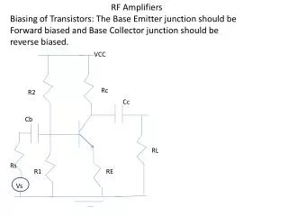
VDD Ld Vb M2 Vin M1 Lg LS LNA Analysis Cascode LNA with inductive source degeneration
Lg Cgb Cgs gmbVsb Zin gmsVgs Z1 Ls Impedance Matching Z1 can be viewed as the parallel of a resistor R with the capacitance Cgs
Simplified small signal model for the LNA matching is achieved simply by making the real part of Zin equal to the source resistance and its imaginary part equal to zero.
Noise Figure Definition LNA small-signal model for noise calculations The noise figure can be expressed as a function of if
Noise figure versus W/L for several inversion levels at 2.5 GHz
LNA Design Example LNA Design Parameters
if=35 Procedure 1. Choice of the inversion level
3. Transistor width for minimum noise figure Noise figure versus W/L for several inversion levels at 2.5 GHz
4. Lg to satisfy the resonance frequency 5. Ld to adjust the gain and the output resonance frequency
RLd Ld Vout M1 RS CL M2 Lg Vin +Vbias Ls LNA Design Results VDD
Simulation results Input impedance
Conclusions • The main advantage of this methodology is that is valid in all regions of the operation of the MOS transistors; • It is possible to move the operation point of RF devices from strong inversion to moderate inversion taking advantage of higher gm/ID ratio, without degrading the noise figure;