Download
1 / 39
390 likes | 503 Views
Interconnect Design Considerations for Large NUCA Caches. Naveen Muralimanohar Rajeev Balasubramonian. Large Caches. Intel Montecito. Cache hierarchies will dominate chip area Montecito has two private 12 MB L3 caches (27MB including L2)

E N D
Interconnect Design Considerations for Large NUCA Caches Naveen Muralimanohar Rajeev Balasubramonian University of Utah
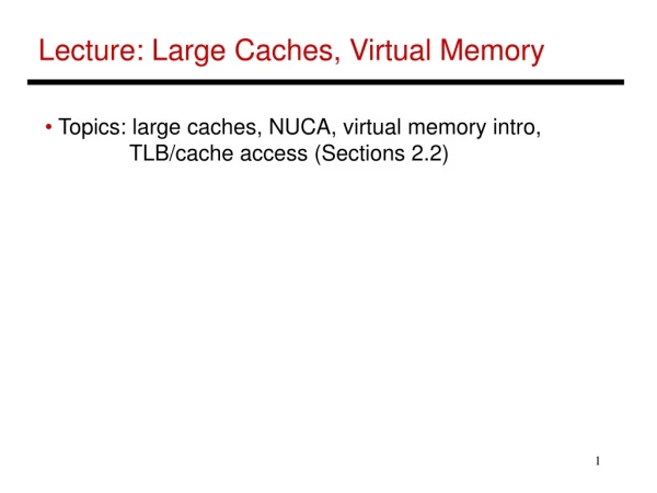
Large Caches Intel Montecito • Cache hierarchies will dominate chip area • Montecito has two private 12 MB L3 caches (27MB including L2) • Long global wires are required to transmit data/address Cache Cache University of Utah
Wire Delay/Power • Wire delays are costly for performance and power • Latencies of 60 cycles to reach ends of a chip at 32nm(@ 5 GHz) • 50% of dynamic power is in interconnect switching (Magen et al. SLIP 04) • CACTI* access time for 24 MB cache is 90 cycles @ 5GHz, 65nm Tech University of Utah *version 3.2
Contributions • Methodology to compute optimal baseline NUCA organization • Performs 51% better than prior NUCA models • Introduce heterogeneity in the network • Additional 15% improvement in performance University of Utah
Cache Design Basics Bitlines Input address Wordline Decoder Tag array Data array Column muxes Sense Amps Comparators Output driver Mux drivers Output driver Data output Valid output? University of Utah
Existing Model - CACTI Wordline & bitline delay Wordline & bitline delay Decoder delay Decoder delay Cache model with 4 sub-arrays Cache model with 16 sub-arrays Decoder delay = H-tree delay + logic delay University of Utah
CACTI Shortcomings • Access delay is equal to the delay of slowest sub-array • Very high hit time for large caches • Employs a separate bus for each cache bank for multi-banked caches • Not scalable Potential solution – NUCA Extend CACTI to model NUCA Exploit different wire types and network design choices to reduce access latency University of Utah
Non-Uniform Cache Access (NUCA)* • Large cache is broken into a number of small banks • Employs on-chip network for communication • Access delay a (distance between bank and cache controller) CPU & L1 Cache banks *(Kim et al. ASPLOS 02) University of Utah
Extension to CACTI • On-chip network • Wire model based on ITRS 2005 parameters • Grid network • 3-stage speculative router pipeline • Network latency vs Bank access latency tradeoff • Iterate over different bank sizes • Calculate the average network delay based on the number of banks and bank sizes • Similarly we also consider power consumed for each organization University of Utah
Effect of Network Delay (32MB cache) Earlier NUCA Model University of Utah
Power Centric Design (32MB Cache) University of Utah
Wire Design Space • Fat, low-bandwidth fast wires • Wires can be tuned for low latency or low power • Low power wires with small, fewer repeaters Global wires B wires 8x plane Semi global wires W wires 4x plane Power optimized PW wires 4x plane Fast, low bandwidth L wires 8x plane University of Utah
Wire Model ores Cside-wall V Wire RC M M M ocap Icap Cadj Ref: Banerjee et al. IEEE TED 2002 65nm process University of Utah
Access time for different link types University of Utah
Cache Look-Up Total cache access time Bank access + Data transfer Decoder, WL, BL (10-15 bits of address) Comparator, output driver delay (rest of the add.) Network delay (4-6 bits to identify the cache Bank) • The entire access happens in a sequential manner University of Utah
Early Look-Up Traditional Access • Send partial address in L-wires • Initiate the bank lookup • In parallel send the complete address • Complete the access Address Lookup Tag + Data transfer L Tag match Early lookup (10-15 bits of address) • We can hide ~70% of the bank access delay University of Utah
Aggressive Look-Up Traditional Access Address Lookup Tag Early Lookup Tag L Aggressive Lookup Early lookup L Full tag entry 1101…1101111100010 11100010 Agg. lookup (additional 8-bits On L-wires for address for partial tag match) Tag match at cache controller University of Utah
Aggressive Look-Up • Reduction in link delay (for address transfer) • Increase in traffic due to false match < 1% • Marginal increase in link overhead • Additional 8-bits • More logic at the cache controller for tag match • Address transfer for writes happens on L-wires University of Utah
Heterogeneous Network • Routers introduce significant overhead (especially in L-network) • L-wires can transfer signal across four banks in four cycles • Router adds three cycles for each hop • Modify network topology to take advantage of wire property • Different topology for address and data transfers University of Utah
Core L2 Controller Router Shared bus Shared bus Shared bus Hybrid Network • Combination of point-to-point and bus • Reduction in latency • Reduction in power • Efficient use of L-wires - Low bandwidth University of Utah
Experimental Setup • Simplescalar with contention modeled in detail • Single core, 8-issue out-of-order processor • 32 MB, 8-way set-associative, on-chip L2 cache (SNUCA organization) • 32KB L1 I-cache and 32KB L1 D-cache with a hit latency of 3 cycles • Main memory latency 300 cycles University of Utah
CMP Setup L2 Bank • Eight Core CMP (Simplescalar tool) • 32 MB, 8-way set-associative (SNUCA organization) • Two cache controllers • Main memory latency 300 cycles C6 C5 C4 C7 C3 C8 C1 C2 University of Utah
Network Model • Virtual channel flow control • Four virtual channels/physical channel • Credit based flow control (for backpressure) • Adaptive routing • Each hop should reduce Manhattan distance between the source and the destination University of Utah
Cache Models University of Utah
Prior work CACTI-L2 Early Aggr. Hybrid. Ideal Performance Results (Uniprocessor) 114% 73% Latency sensitive benchmarks - ~70% of the SPEC suite University of Utah
Prior work CACTI-L2 Early Aggr. Hybrid. Ideal Performance Results (Uniprocessor) 26% 20% 8% 9% 19% 15% 6% 8% Latency sensitive benchmarks - ~70% of the SPEC suite University of Utah
Performance Results (CMP) University of Utah
Performance Results (4X – Wires) Wire delay constrained model • Performance improvements are better • Early lookup - 7% • Aggressive model - 20% • Hybrid model - 29% University of Utah
Conclusion • Network parameters play a significant role in the performance of large caches • Modified CACTI model, that includes network overhead performs 51% better compared to previous models • Methodology to compute an optimal baseline NUCA University of Utah
Conclusion • Wires can be tuned for different metrics • Routers impose non-trivial overhead • Address and data have different bandwidth needs • We introduce heterogeneity at three levels • Different types of wires for address and data transfers • Different topologies for address and data networks • Different architectures within address network (point-to-point and bus) (Yields an additional performance improvement of 15% over the optimal, baseline NUCA) University of Utah
Prior work CACTI-L2 Early Aggr. Hybrid. Ideal Performance Results (Uniprocessor) Model derived from CACTI, improvement over model assumed in the prior work – 73% L2 Sensitive – 114% Model derived from CACTI, improvement over model assumed in the prior work – 73% L2 Sensitive – 114% University of Utah
Prior work CACTI-L2 Early Aggr. Hybrid. Ideal Performance Results (Uniprocessor) Early lookup technique, average improvement over Model 2 – 6% L2 Sensitive – 8% University of Utah
Prior work CACTI-L2 Early Aggr. Hybrid. Ideal Performance Results (Uniprocessor) Aggressive lookup technique, average improvement over Model 2 – 8% L2 Sensitive – 9% University of Utah
Prior work CACTI-L2 Early Aggr. Hybrid. Ideal Performance Results (Uniprocessor) Hybrid model, average improvement over Model 2 – 15% L2 Sensitive – 20% University of Utah
Outline • Problem Overview • Cache Design Basics • Extensions to CACTI • Effect of Network Parameters • Wire Design Space • Exploiting Heterogeneous Wires • Results University of Utah
Outline • Problem Overview • Cache Design Basics • Extensions to CACTI • Effect of Network Parameters • Wire Design Space • Exploiting Heterogeneous Wires • Results University of Utah
Outline • Problem Overview • Cache Design Basics • Extensions to CACTI • Effect of Network Parameters • Wire Design Space • Exploiting Heterogeneous Wires • Results University of Utah
Outline • Overview • Cache Design • Effect of Network Parameters • Wire Design Space • Exploiting Heterogeneous Wires • Methodology • Results University of Utah
Aggressive Look-Up Full tag entry Way 1 1101…1101111100010 L Way n 1101…1101111100010 Agg. lookup (additional 8-bits of address for partial tag match) Tag match at cache controller 11100010 University of Utah