Download
1 / 70
780 likes | 1.27k Views
Fire Pump Theory. Sugar Land Fire Department Driver/Operator—Pumper Academy Spring 2003. Fire Pump Theory. Positive Displacement Pumps. Have largely been replaced by centrifugal pumps for use as the main fire pump on modern apparatus. Can pump air

E N D
Fire Pump Theory Sugar Land Fire Department Driver/Operator—Pumper Academy Spring 2003
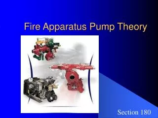
Positive Displacement Pumps • Have largely been replaced by centrifugal pumps for use as the main fire pump on modern apparatus. • Can pump air • Operate on the hydraulic law that when pressure is applied to a confined liquid, the same outward pressure is transmitted outward and equally in all directions within the liquid • Come in two basic types; piston & rotary
Multicylinder, High Pressure • Are still in use today to provide pressures up to 1,000 psi for high pressure fog lines. • Are commonly used in wildland fire fighting • Require a dependable relief valve; if discharge flow is interrupted, pressures quickly build to dangerous levels
Rotary Gear Pumps • Total amount of water than can be pumped dependent on gear pocket size and rotation speed • Require a pressure relief valve • Are very susceptible to damage from normal wear and tear • Are very susceptible to damage from pumping contaminated water
Rotary Vane Pumps • Not as susceptible to damage from normal wear and tear as are rotary gear and piston types • Automatically adjust: when surface of a vane in contact with casing becomes worn, centrifugal force causes it to extend further, thus automatically maintaining a tight fit.
Changeover • Changeover is the process of switching the transfer valve on the pump between pressure and volume. • Fire service changeover rule of thumb—leave transfer valve in the pressure position until it is necessary to supply more than ½ the rated volume capacity of the pump. • Manufacturer’s changeover recommendation—leave transfer valve in pressure position until it is necessary to flow more than 2/3 the rated volume capacity of the pump
Changeover • Consult operator’s manual for recommended flow rate at which transfer should occur • Consult the operator’s manual for the maximum net pup discharge pressure at which the transfer valve can be operated • Because there may be a slight interruption to fireground operations when changeover occurs, coordinate changeover with attack crews so that line are not shut down at critical times.
Changeover • Try to anticipate the requirements that will be placed on the pumper as the fire fighting operation progresses, and have the transfer valve in the proper position from the start. • If there is any question as to the proper operation of the transfer valve, it is better to be in parallel than in series • Know that there is a built-in safeguard that makes it impossible to accomplish manual transfer while the pump is at high pressure on many two-stage pumps, particularly on older pump models.
Changeover • Use special care when operating the high-pressure power-activated transfer valves found on newer pumps. • Whenever possible equip the power control on power activated transfer valves with some sort of manual override to allow the transfer to be operated should the power equipment fail.
Pump Wear • A very close tolerance must be maintained between the pump casing and the hub of the impeller to prevent water from escaping back into the intake • Impurities in the water supply accelerate pump wear by acting like sandpaper in wearing down metal surfaces. • As the gap between the pump casing and impeller hub increase through wear, greater amounts of water escape to the intake
Pump Wear • To restore pump capacity and maintain the proper spacing between the pump casing and impeller hub, the driver/operator should replace the wear rings. • If the impeller hub is also worn down, it is possible to install smaller wear rings to compensate for the smaller size and maintain clearance. • Ensure that some water is running through the pumps at all times to prevent overheating and possible pump damage.
Pump Wear • Check the pump temperature by placing a hand on the direct pump intake pipe; if it is warm to the touch, open a discharge or circulator valve. • It is best for the driver/operator not to run the pump with the discharges closed for any extended period; if no water is expected to be discharged for an extended period of time, disengage the pump until it is needed.
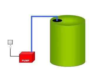
Pump Piping & Valves • Intake Piping • Pumpers with a capacity of 500 gpm should be able to flow at least 250 gpm from the booster tank. • Pumpers with capacities greater than 500 gpm should be able to flow at least 500 gpm • Many pumpers today are equipped with tank-to-pump lines as large as 4” in diameter • Mobile water supply units may have multiple small-diameter tank-to-pump lines.
Pump Piping & Valves • The lines to all modern pumps are equipped with check valves that make it impossible to fill the tank through the pump by opening the tank-to-pump valve • To prevent air from being trapped in the pump during priming operations, all intake lines to centrifugal pumps are normally located below the impeller eye, and no part of the piping is above this point. • The primary intake is large-diameter piping and connections.
Pump Piping & Valves • Large diameter intake piping is round where the hose connects to it but tapers, as it nears the pump, to a square shape to eliminate the vortex that occurs in round piping. • Additional large-diameter intake may be piped to the front or rear of the apparatus. • Front and rear intakes should be considered auxiliary intakes. • Pumps with a capacity of 1,500 gpm or greater may require more than one large intake connection
Pump Piping & Valves • Additional intake lines, usually gated, are provided for use in relay operations or anytime water is being received through small-diameter supply lines. • Most small-diameter intake openings are threaded for 2 ½ hose couplings • If 2 ½ pipe contains 90 degrees bends or T-fittings, friction loss may limit flow to 250 gpm • 3” pipe is capable of flowing as much as 450 gpm if care is given to the fittings.
Pump Piping & Valves • Must be enough 2 ½ or larger discharge outlets to flow rated capacity of pump • Apparatus with a rated pump capacity of 750 gpm or greater must be equipped with at least two 2 ½” discharges • Apparatus with a rated pump capacity less than 750 gpm are required to have only one 2 ½” discharge • Discharges larger than 2 ½” may not be located directly on the pump operator’s panel.
Pump Piping & Valves • Apparatus may be equipped with 1 ½, 1 ¾, and 2” discharges • Discharges 2” and smaller must be supplied by at least a 2” piping • To prevent movement, the discharge locking ball valve should be kept locked when the discharge is open. • All valves are designed to be easily operated at pressures up to 250 psi.
Pump Piping & Valves • Tank Fill Lines • Should be located on discharge side of pump • Allows tank to be filled without making any additional connections • Provides a means of replenishing the water carried in the tank • Requires a tank fill line with a diameter of at least 1” on apparatus with water tanks less than 1,000gals per NFPA 1901
Pump Piping & Valves • Requires a tank fill line with a diameter of at least 2” on apparatus with water tanks 1000gals or larger Per NFPA 1901 • Can be used to circulate water through pump to prevent overheating when no lines are flowing
Pump Cooling • Tank Fill Line • Circulator Valve • Booster line cooling valve • Waster/dump line
Valves • Push/pull Handle (T-handle) • Allows easy operation of valve under pressure • Allows driver/operator to set precise pressure values when adjusting individual lines • Can be mounted in a position remote from pump panel. • Can usually be locked in any position with a 90 degree twist of the handle • Must be pulled straight out to prevent binding the shaft • Used to actuate ball valves
Valves • Quarter-Turn Handle • Has simple mechanical linkage mounted directly on valve stem • Opens and closes valve with 90 degree movement of handle • May be locked by raising or lowering the handle, but newer versions lock automatically when handle is released or when handle is rotated clockwise • Used to actuate ball valves and butterfly valves
Valves • Toggle Switch • Found on newer apparatus • Visually display a readout of how far the valve is opened • Indicated through panel markings which direction to operate the switch to open and close the valve • Used to actuate ball valves
Valves • Handwheel—most commonly used to actuate gate valves
Pump Drain and Bleeder Valves • Drain Valves • Provides a way for driver/operator to relieve pressure from hoseline after discharge valve and nozzle have been closed • Useful when hose has not been bled off and is a great distance from apparatus • Allows for draining and disconnecting unused lines even when the pump is still in service • Allows for all water to be removed from the system in freezing climates • When connected to master drain valve, pump and piping can be drained in one operation.
Pump Drain and Bleeder Valves • Bleeder valve on gated intake • Allows air to be removed from system before it enters fire pump • Makes it possible to change over to the supply line without interrupting fire streams: • 1. Wait until all air is evacuated form line and bleeder valve is discharging a steady stream of water • 2. Close the drain valve • 3. Open the intake valve • 4. Close the tank-to-pump valve
Automatic Pressure Control Devices • Discharge pressure relief valve—relieves excess pressure within the pump discharge
Automatic Pressure Control Devices • Intake pressure relief valve—prevents damage to pump and discharge hoselines when valves/nozzles are closed too quickly • Integral pressure relief valve—part of pump intake manifold; relieves pressure on intake side of pump • Screw-on pressure relief valve—add-on device screwed onto pump intake connection; relieves pressure on intake side of pump