Download

1 / 21
210 likes | 216 Views
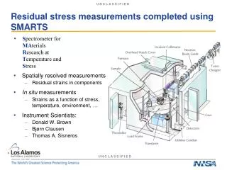
Residual B-Field Measurements in Vacuum Tank . Michael E. Nelson. Michael E. Nelson. 3. Programme of Measurements. Sensor developed (Felix Bergsma) to measure B-field. Sensor contains 3 Hall probes, each measuring one of the x,y,z-components of the B-field.

E N D
Residual B-Field Measurements in Vacuum Tank Michael E. Nelson
Michael E. Nelson 3. Programme of Measurements • Sensor developed (Felix Bergsma) to measure B-field. • Sensor contains 3 Hall probes, each measuring one of the x,y,z-components of the B-field. • Need to determine sensor offsets which are self-consistent and agree on the value of the true field. Summary Beam + Infrastructur
Michael E. Nelson 4. Consideration of Systematic Errors • Three main sources of error contribute to ∫B.dl: 1) Measurement error – statistical error on individual measurements contributes ~100 µT.m 2) Sampling error – systematic error due to length sampling at ~ every 3m, rather than sampling continuously: 150 – 250 µT.m 3) Offset error – systematic error due to a single offset calibration of the sensor. ~700 µT.m for an uncertainty in offset of 10 µT Since the total error contribution must be < 1000μTm this cautions against the use of a single offset calibration for all data. Summary Beam + Infrastructur
Michael E. Nelson 6 New Sensor Programming • Modification (Felix Bergsma): the revised software calculates the mean of the offset distribution as the new electronic correction to the Hall probes. • When switched on, the device samples the offsets 25 times and takes an average. This average was found to be stable to ~5 µT. • Despite the stability of the offset being improved, there remained problems with stability due to temperature changes in the local environment. The offsets measured at different times and places were markedly different. It was therefore crucial to check that the measured offsets were stable during the measurement of B_Fields. • This was done by measuring the offsets before and after B-field readings in situ and checking for consistency between the two sets. Care was taken not to switch the instrument off/on during the measurement cycle. Summary Beam + Infrastructur
Michael E. Nelson 7 Revised Measurement Procedure • At each Z, the sensor offsets are measured for the x, y, z-Hall probes • B_fields are then measured at the different positions on the chosen grid, with sufficient sets of readings to check for consistency and enable a sensible uncertainty to be calculated. • The sensor offsets for the x, y, z Hall probes are then remeasured and if consistent with the first set of offsets, the data taken at each point on the grid are validated. • This procedure gives independent values of offsets, with good estimates of the systematic error that applies to the measurements at any particular value of Z. Summary Beam + Infrastructur
Michael E. Nelson Grid Structures Inner diameter < 2000mm Inner diameter > 2000mm Summary Beam + Infrastructur
Michael E. Nelson Key Points • Measuring residual magnetic fields with the required accuracy and precision is non trivial and requires a good understanding of the instrumentation and the environment in which it is used. • Much data has been taken in May and July and inconsistencies found, which render it useless. • Improvements to the use and function of the instrument now give stable, reproducible data of high quality and precision. • In a revised procedure the systematic error in the offset is added linearly to the B_field measurement uncertainties at each Z. The uncertainty in ∫B.dl is then obtained by combining in quadrature the contributions at each Z. • The overall uncertainty in ∫B.dl is will be well within specification. Summary Beam + Infrastructur
B-Field Mapping Liverpool 28-08-2013
Magnet Mapping Bench Two measurement series (upstream/downstream side Outside tube Inside tube 1.5m 3.0m Summary Beam + Infrastructur Felix Bergsma, Francois Garnier + Piere-Ange Giudici,
Mapping Bench Installed and aligned on upstream side Summary Beam + Infrastructur
Sensor Panel 80 2 sensor layers in Z 80 80 295 800 60 3D Hall probes (3 x 10 per plane) Summary Beam + Infrastructur
Measurement Grid Foresee: 100 measurement positions in z (every 8 cm => ΔZ=4cm) No. of points 60x100x19 = 114’000 (Z position can be multiples of 4cm) Summary Beam + Infrastructur
Planning • The measurement starts on Sept. 9th and must be finished by Sept. 26th (before open-day WE) • We might need volunteers for operating the measurement bench. Summary Beam + Infrastructur
Lau Gatignon The issues observed in the TR Skew horizontal profilesin the CEDAR region Some 20% missing K+ Note: no horizontal bends in this part of the beam line! Summary Beam + Infrastructur
Lau Gatignon What did we check / consider • We dismounted the roof shielding over the front end and the surveyors checked the alignment of all elements. All was found to be correct. • A special rod was inserted into the TAX and their relative alignment was found correct to better than 1 mm. • We inserted a tool in the TAX and looked at it directly. Also OK to a fraction of a millimeter. • The surveyors checked the alignment of all elements in the front-end from thelocation of the second MTR (which had to be dismounted anyway to be turnedby 180 degrees). They found all correct within about 0.3 mm. • The overall beatch axis was checked (for conceptual bugs in the transformationfrom old to new coordinates) and was found correct. See next slide • A tool was inserted into a ‘fixed’ collimator in T10. A 60 mm diameter insert has a t 20 mm diameter hole, offset. This piece was found to be rotating freely and could have been at any azimuthal angle. This will be fixed correctly next year. Summary Beam + Infrastructur
Lau Gatignon Coherence check of different Beatch axes Summary Beam + Infrastructur
Lau Gatignon Results of measurements in 2013: Summary Beam + Infrastructur
Lau Gatignon So what can we do? • We could not check the alignment of T10 itself. We know that the TBIU of T10 is off by about 5 mm, due to a mechanical deformation of its support. • T10 itself will be consolidated before the 2014 run: new target box, new monitors, overhaul of all the mechanics. If there was a problem, we should find it and fix it. • In 2014 we will have to take some time to fully re-tune the beam carefully. Summary Beam + Infrastructur
Lau Gatignon Other open issues for the 2014 run • The double wall separating TCC8 from ECN3 has to be installed and the access system integrated with it. See next slide • The ventilation system upgrade will only be done in 2015, but the pressurization of the double wall and some minimal provisional measures to separate TCC8 from ECN3 will be done before the 2014 run. Also the interlocks on the DP in the air locks at the bottom of PPG853 and 854 will be activated. • Extra money has been obtained to complete the vacuum system. Only the fast valve funding is still an open issue. • The expansion vessel remains to be installed next to the CEDAR. • The H2 infrastructure must be completed. • The TCC8 crane refurbishment is still not guaranteed to be financed. • The access to the dump via the dump tunnel will be fenced off. • Last but not least: a thorough upgrade of CESAR is planned. Summary Beam + Infrastructur
Lau Gatignon Fast Vacuum Valve Mitigate risk related to KTAG Beam Windows Al Window thickness: Upstream end 150 mm Downstream end 200 mm KTAG GTK’s LKR Summary Beam + Infrastructur
Lau Gatignon KTAG Window Protections Decisions to be made • Fast Valve (Downstream side) • Cost 30kCHF Proposed sharing 50/50 = CERN / NA62 15k to be financed by collaboration • Buffer Volume (Upstream side) • Requires modification on “fond bombée” Summary Beam + Infrastructur