Download
1 / 19
190 likes | 209 Views
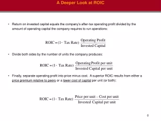
A Deeper Look at LTE. Iyappan Ramachandran Agilent Technologies May 20, 2010. Cellular Comms Evolution. LTE. 3GPP – collaboration for 3G based on GSM 3GPP2 – collaboration for 3G based on IS-95. LTE PHY Basics. Six bandwidths 1.4, 3, 5, 10, 15, and 20 MHz Two modes FDD and TDD

E N D
A Deeper Look at LTE IyappanRamachandran Agilent Technologies May 20, 2010
Cellular Comms Evolution LTE • 3GPP – collaboration for 3G based on GSM • 3GPP2 – collaboration for 3G based on IS-95
LTE PHY Basics • Six bandwidths • 1.4, 3, 5, 10, 15, and 20 MHz • Two modes • FDD and TDD • 100 Mbps DL (SISO) and 50 Mbps UL • Transmission technology • OFDM for multipath resistance • DL OFDMA for multiple access in frequency/time • UL SC-FDMA to deal with PAPR ratio problem
Frame Structure Frame Structure Type 1 (FDD) Frame Structure Type 2 (TDD)
: : Resource grid One downlink slot, Tslot • 6 or 7 OFDM symbols in 1 slot • Subcarrier spacing = 15 kHz • Block of 12 SCs in 1 slot = 1 RB • 0.5 ms x 180 kHz • Smallest unit of allocation 6 or 7 OFDM symbols Resource block Transmission BW Resource element 12subcarriers l=0 l=6
2-D time and frequency grid #19 #18 #17 #16 1 radio frame = 10 msec (307200 x Ts) Time #5 #4 #3 #2 Sub-frame #1 NscRB subcarriers (=12) #0 Power 1 slot = 0.5 msec Frequency NBWDL subcarriers
DL PHY Channels and Signals • Signals: generated in PHY layers • P-SS: used for initial sync • S-SS: frame boundary determination • RS: pilots for channel estimation and tracking • Channels: carry data from higher layers • PBCH: broadcast cell-specific info • PDCCH: channel allocation and control info • PCFICH: info on size of PDCCH • PHICH: Ack/Nack for UL blocks • PDSCH: Dynamically allocated user data
QPSK 16QAM 64QAM P-SCH - Primary Synchronization Signal S-SCH - Secondary Synchronization Signal PBCH - Physical Broadcast Channel PDCCH -Physical Downlink Control Channel PDSCH - Physical Downlink Shared Channel Reference Signal – (Pilot) Time Frequency DL Channel Mapping
DL signal demo (1) DL 5 MHz FDD signal in AWGN channel
DL signal demo (2) DL 5 MHz FDD signal in frequency-selective channel
UL PHY Signals and Channels • Signals: generated in the PHY layer • Demodulation RS : sync and channel estimation • SRS: Channel quality estimation • Channels: carry data from higher layers • PUSCH: Uplink data • PUCCH: UL control info • PRACH: Random access for connection establishment
PUSCHDemodulation Reference Signal(for PUSCH) PUCCH Demodulation Reference Signal(for PUCCH format 0 or 1, Normal CP) UL Channel Mapping 64QAM16QAMQPSK QPSK BPSK Time Frequency
UL signal demo UL 5 MHz FDD signal in AWGN channel
MIMO in LTE • Rel 8 defines MIMO only for DL • 1, 2 and 4 transmit antennas defined for • Transmit Diversity (TxDiv) • Spatial Multiplexing (SpMux) • Control channels undergo TxDiv based on SFBC • Data channels may undergo TxDiv or SpMux
Orthogonal RS locations • channel matrix needs to be known in advance for equalization
DL MIMOsignal demo DL 5 MHz TDD 4x2 MIMO signal in frequency-selective channel