Download

1 / 55
580 likes | 639 Views
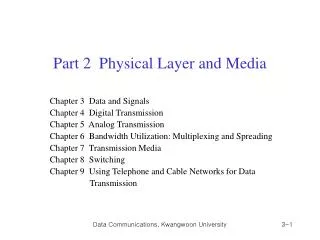
Part II. Physical Layer and Media. Chapter 4. Digital Transmission. COMP 3270 Computer Networks Computing Science Thompson Rivers University. Chapter Contents. Digital-to-digital conversion Analog-to-digital conversion Transmission mode. Learning Objectives.

E N D
Part II. Physical Layer and Media Chapter 4. Digital Transmission COMP 3270 Computer Networks Computing Science Thompson Rivers University
Chapter Contents • Digital-to-digital conversion • Analog-to-digital conversion • Transmission mode
Learning Objectives • Determine the baud rate from a given bit rate and the number of signal elements for sending one bit, assuming line coding. • Identify the three problems caused by a long string of 0s and1s. • Explain the basic idea to solve the above three problems. • Identify advantages and disadvantages of Manchester and differential Manchester line coding schemes, comparing to NRZ coding scheme. • Describe the motivation of block coding. • Describe the basic idea of PCM that converts an alalog signat to digital data. • Use of the Nyquist Theorem to decide the minimum sampling rate. • Distinguish parallel and serial transmission modes.
1. DIGITAL-TO-DIGITAL CONVERSION In this section, we see how we can represent digital data by using digital signals. The conversion involves two techniques: line coding, and block coding. Line coding is always needed; block coding may or may not be needed. Topics discussed in this section: • Line Coding • Line Coding Schemes • Block Coding
Line Coding Line coding and decoding The process of converting binary data, a sequence of bits, to a digital signal.
Signal element (or signal level) versus data element Data rate (or Bit rate), Baud rate) (Text book)
Example: A signal is carrying data in which one bit is encoded as one signal element (r = 1). If the bit rate is 100 kbps, what is the baud rate? Solution:
Consecutive bit 0s or 1s may cause serious problems in digital transmission. • Baseline Wandering • DC Component • Lack of Self-Synchronization • We need good encoding schemes.
Baseline Wandering (at the receiver) • The average of the received signal power – baseline • Incoming signal power is evaluated against this baseline to determine the value of the data element. A long string of 0s or 1s can cause a drift in the baseline. • A good line coding scheme needs to prevent baseline wandering. One example:
DC Components • When the voltage level in a digital signal is constant for a while, the spectrum creates very low frequencies around zero, called DC (Direct Current) components. • Cannot pass the band pass channels, e.g., a telephone line cannot pass frequencies below 200 Hz.
Self Synchronization • Correct bit intervals at the sender and the receiver are critical. • A self-synchronizing digital signal includes timing information in the data being transmitted, which is transitions of the signal.
Unipolar NRZ scheme ☺ Are all the three problems solved?
Polar NRZ-L and NRZ-I schemes N ☺ Are all the three problems solved?
In NRZ-L the level of the voltage determines the value of the bit. In NRZ-I the inversion or the lack of inversion determines the value of the bit.
NRZ-L and NRZ-I both have the baud rate of N Bd. ☺ Are all the three problems solved?
NRZ-L and NRZ-I both have a DC component problem. • ☺ Baseline Wandering? • ☺ DC Component? • ☺ Lack of Self-Synchronization?
Example: A system is using NRZ-I to transfer 10-Mbps data. What are the baud rate and minimum bandwidth? Solution: The average baud rate is S = N = 10-Mbaud/sec. The minimum bandwidth for this baud rate is Bmin = S/2 = 5- MHz.
Polar RZ (Return-to-Zero) scheme 2N • ☺ Baseline Wandering? • ☺ DC Component? • ☺ Lack of Self-Synchronization? • ☺ Bandwidth consumption?
Polar biphase: Manchester and differential Manchester schemes Ethernet 2N Token ring
The minimum bandwidth of Manchester and differential Manchester is 2 times that of NRZ. ☺ Why is it important?
Summary of line coding schemes ☺ How to combine?
Block Coding Block coding is normally referred to as mB/nB coding; it replaces each m-bit group with an n-bit group, so that there are not long 0s or 1s.
Using block coding 4B/5B with NRZ-I line coding scheme 100 Base T: 4B/5B + NRZ-L FDDI: 4B/5B + NRZ-I
4B/5B mapping codes The length of the longest 1s is ???.
Example: We need to send data at a 1-Mbps rate. What is the minimum required bandwidth, using a combination of 4B/5B and NRZ-I, or Manchester coding? Solution: First 4B/5B block coding increases the bit rate to 1.25 Mbps. The minimum bandwidth using NRZ-I is N/2 or 625 KHz. The Manchester scheme needs a minimum bandwidth of 1 MHz. The first choice needs a lower bandwidth, but has little DC component problem; the second choice needs a higher bandwidth, but does not have a DC component problem.
Intermediate Summary • Bit rate vs. baud rate • Four problems caused by consecutive 0's and 1's • The problem of Manchester scheme • How block coding works
2. ANALOG-TO-DIGITAL CONVERSION In this section we describe one technique, pulse code modulation. Topics discussed in this section: • Pulse Code Modulation (PCM)
Pulse Code Modulation (PCM) ☺ Any good idea to load an analog signal over a digital signal? (How to send analog information using a digital signal?)
Components of PCM encoder – conversion of an analog signal to diginal data
According to the Nyquist theorem, the sampling rate must be at least 2 times the highest frequency contained in the signal.
Example: Telephone companies digitize voice by assuming a maximum frequency of 4000 Hz. The sampling rate therefore is 8000 samples per second. If a byte is used to express a sample (i.e., strength), then we need the data rate: 64 Kbps = 8 bits / sample 8000 samples / sec for all the samples for a second. Audio CD: (20Hz – 20KHz) -> 44.1 K sampling rate; 16 bits / sample -> 705.6 Kbps
Example: A complex low-pass signal has a bandwidth of 200 KHz. What is the minimum sampling rate for this signal? Solution: The bandwidth of a low-pass signal is between 0 and f, where f is the maximum frequency in the signal. Therefore, we can sample this signal at 2 times the highest frequency (200 KHz). The sampling rate is therefore 400,000 samples per second.
Example: A complex band-pass signal has a bandwidth of 200 kHz. What is the minimum sampling rate for this signal? Solution: We cannot find the minimum sampling rate in this case because we do not know where the bandwidth starts or ends. We do not know the maximum frequency in the signal.
Quantization Error 9.3 8.8
7.0 8.8 9.3 6.0
7 9 9 6
Some sort of noise, called sampling noise, is induced. Reproduction of the original signal
Example: We want to digitize the human voice. What is the bit rate, assuming 8 bits per sample? Solution: The human voice normally contains frequencies from 0 to 4000 Hz. So the sampling rate and bit rate are calculated as follows:
Intermediate Summary • The idea of PCM • 3 components of PCM • Nyquist theorem • Sampling noise
3. TRANSMISSION MODES The transmission of binary data across a link can be accomplished in either parallel or serial mode. In parallel mode, multiple bits are sent with each clock tick. In serial mode, 1 bit is sent with each clock tick. While there is only one way to send parallel data, there are three subclasses of serial transmission: asynchronous, and synchronous. Topics discussed in this section: • Parallel Transmission • Serial Transmission