Download
1 / 43
430 likes | 601 Views
P10236 Project Review. Project Review. MSD Project 10236. Joe Pinzone Alex Mykyta Roberto Stolfa Robert Ghilduta Jason Stanislawski. Configurable Control Platform for Unmanned Vehicles. P10236 Project Review. Customer Needs (condensed).

E N D
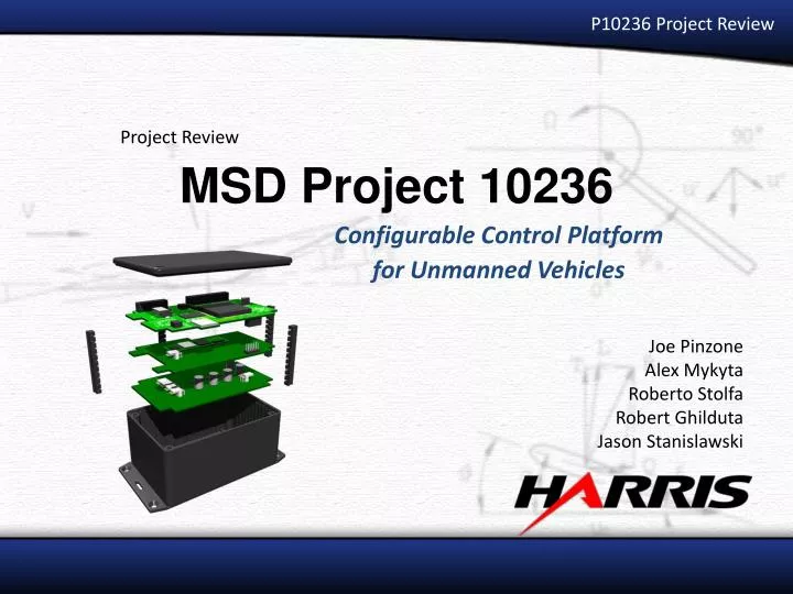
P10236 Project Review Project Review MSD Project 10236 Joe Pinzone Alex Mykyta Roberto Stolfa Robert Ghilduta Jason Stanislawski Configurable Control Platform for Unmanned Vehicles
P10236 Project Review Customer Needs (condensed) • Compiles, stores and executes control models from MATLAB Simulink® • Interfaces with UAV sensors, servo-actuators, and future wireless link • External monitoring of system data • Supports data logging to removable storage • Extended set of I/O capabilities for expansion to other vehicle platforms
P10236 Project Review Constraints • Physically fits into and mounts to UAV C • Powered from (unregulated) battery source • Operates for duration of 30-minute mission • Serviceable “in-field” with limited set of tools • Open-source, open-architecture solution that does not require expensive proprietary licensing to develop, produce, or use
P10236 Project Review Specifications (condensed)
P10236 Project Review Selected Concept • Four Independent, Interconnected Sub-systems • Input / Output Controller (IOC) • Control Code Processor (CCP) • Power Regulation Module (PRM) • Input / Output Breakout Board (IOB) – not pictured • Physically separable, swappable modules • Allows each sub-system design to be idealized for performing each task IOC CCP PRM
CCP – Control Code Processor • Stores & executes Simulink-generated control code • Gumstix Overo® Water Specs & Features: • ARM Cortex-A8 @ 600 MHz • TMS320C64x+ DSP @ 430 MHz • RAM: 256MB mDDR SDRAM (2.7 GByte/s) • Flash: 256MB NAND • Card slot: microSD/SDHC • Size: 0.67 in. x 2.28 in. 0.16 in.
IOC – Input/Output Controller • Arbitration of peripheral communication and data I/O • Dual port RAM for easy data sharing • Connects to CCP using a dedicated high speed SPI bus • Can operate asynchronously and independently from CCP • Features: • Up to 5 (each) SPI & UART controllers (space reserved for future I2C controllers) • Up to 40 GPIO pins compatible with 1.65 to 5.5v logic levels • 16 channel multiplexed 16-bit ADC with 3.0v reference. 256 kSPS • 8 PWM input & 8 PWM output channels • 32 kB internal RAM + 512 kB external SRAM • 4MB FLASH program storage memory • Micro-SD card socket for data logging • Configurable through USB Micro-SD Card Spartan 3E FPGA SRAM Power & Power-good status USB Port JTAG Level Shifters Digital IO & PWM Header Analog Header
P10236 Project Review Input / Output Breakout Board (IOB) • Purpose: • FPGA pin breakout • - Sensor routing • - Signal conditioning • Control switching • - Hobby receiver (manual) • - IOC control (autonomous) • IOC Testing • Swappable peripheral sets • - UAV set (pictured) • - Platform specific • - Various IOB’s can be connected Analog Header Digital Header Power In and Battery monitor headers IMU Analog Sensors GPS Servo Output Header R/C Receiver Header Airspeed Sensor Temperature Sensor
End User Workflow Yes Yes
P10236 Project Review Power Regulation Module (PRM) • Designed around TI Power Controller • TPS43000 PWM • SEPIC topology • More advantageous than LDO solution • Provides three system power rails • 3.3V (I/O Controller) • 3.6V (Control Code Processor) • 5.0V (I/O Breakout Board) • Maximizes input voltage range • Final rev. includes 3V “Jump-starter” battery • Allows startup of IC with low-voltage supply
Metrics #1 and #2Power Efficiency / Input Voltage Range Test Overview • Connect Power Regulation Module (PRM) to: • a Laboratory power supply • a test load • Measure: • Power supply output current • PRM output current • PRM output voltage • Calculate efficiency • Measurements repeat over the range of test loads Metric 1 • PASS = 80% efficiency over operating load and input voltage ranges • FAIL = < 80% efficiency over operating load and input voltage ranges Metric 2 • PASS = Regulated output within 5% of nominal Voutput for Vinput between 4.6V - 5.8V • FAIL = Regulated output not within 5% of nominal Voutput for Vinput between 4.6V - 5.8V
Metric #1 Power Efficiency Metric 1 • PASS = 80% efficiency over operating load and input voltage ranges • FAIL = < 80% efficiency over operating load and input voltage ranges
Metric #2 Input Voltage Range Metric 2 • PASS = Regulated output within 5% of nominal Voutput for Vinput between 4.6V - 5.8V • FAIL = Regulated output not within 5% of nominal Voutput for Vinput between 4.6V - 5.8V
Metric #3Guaranteed Operating Time Test Overview • The Power Regulation Module (PRM) is connected to a test load. • connect a charged Ni-MH battery pack • Measure energy consumed after 30 minutes Metric 3 • PASS = After 30 minutes, no more than 2/3 battery capacity is used • FAIL = After 30 minutes, more than 2/3 battery capacity is used
Metric #4Provides Mounting Points to Vehicle Metric 4 • PASS = Product provides mounting holes to accept mounting hardware. Holes are predrilled, or a surface is designated for drilling for mounts. Mount is appropriate for attachment to flat surface. • FAIL = No mounting points are supplied, and there are no proper places to drill and attach the product to a flat surface
Metric #5Total System Weight Test Overview • Weigh total System Metric 5 • PASS = Product < 3 lbs in weight • FAIL = Product >= 3 lbs in weight Final Weight (with IOB) = 0.76 lbs
Metric #6Operates over expected temperature Test Overview • Heat running system to 38 degrees C, monitor for crashes or errors • Cool system as low as possible (-20C desired), monitor for crashes or errors Metric 6 • PASS = All sub-systems operate without errors for -20C to 38C • FAIL = System crashes while within desired temperature range of -20C to 38C
Metric #7Ports are externally accessible Metric 7 • PASS = System power and programming ports can be accessed without removing any part of the system from vehicle • FAIL = System must be removed in some way to access ports Metric #8Compatible Simulink Blocks Metric 8 • PASS = Model successfully builds, compiles, and runs on CCP • FAIL = Model can not be successfully built, compiled, and executed.
Metrics #9 and #10I/O Throughput / Control Processing Bandwidth Test Overview • Run MAV II control model on CCP (1000Hz model) • Acquire IOC sensor data for UAV at 1000 Hz • Verify no errors Metric 9 • PASS = The IOC and I/O cores execute control model with throwing overflow errors • FAIL = The IOC or the I/O cores overflow when data request rate is 1000 Hz Metric 10 • PASS = The CCP does not throw any overflow errors during code execution at 1000 Hz • FAIL = The CCP throw overflow errors during code execution at 1000 Hz
Metric #11Non-volatile storage for control code Test Overview • Upload compiled Simulink control code to CCP • Reboot CCP and see if model is still on system Metric 11 • PASS = The CCP boots and runs control code without re-programming • FAIL = The CCP is unable to boot and run control code without reprogramming
Metric #12Architecture bit length/accuracy Test Overview • Connect power to IOB analog header • Request ADC value • Show returned value Metric 12 • PASS = ADC output is 16-bits • FAIL = ADC output is less than 16-bits
Metric #13System can use external data in control code Test Overview • Run Simulink model with input looped back to drive one of the PWM outputs proportional to the input value • Connect hobby servo to the PWM output on the IOB • Write a value to the shared memory, show servo move after each command (Mimics operation of telemetry unit) Metric 13 • PASS = Manually-entered data successfully affects servo output • FAIL = External data cannot be used by control code processor
Metric #14I/O peripheral set is configurable Metric 14 • PASS = Types and numbers of I/O types are readily configurable in the user interface • FAIL = The user cannot change the set of peripherals attached to the system
Metric #15All source data is freely available and documented Metric 15 (a) • PASS = The software and data used to construct the final product is openly available to the public. The re-generation of the product does not require any software that requires a license to use, except the specific case of MATLAB Simulink RTW. Code format and commenting is clean and clear • FAIL = The use or reproduction of the system requires the licensing of proprietary technology from one or more third-parties. Code is messy, uncommented. Metric 15 (b) • PASS = The procedure can be reliably reproduced using the instructions in the documentation • FAIL = The product cannot be used with only the instructions provided
Metric #16I/O peripherals connect externally Metric 16 • PASS =Control Platform can be removed from vehicle without the need to also remove attached vehicle sensors or other peripherals • FAIL =Removal of the Control Platform requires the otherwise unnecessary removal of one or more of the other vehicle peripherals
Metric #17Physical Size Metric 17 • PASS = Total system package fits within the allocated space on Airframe C • FAIL = Total system does not fit in allocated space on Airframe C
Metric #18Provide interface to telemetry Metric 18 • PASS = Final design is demonstrated to be able to communicate via UART, and collaboration has taken place to guarantee compatibility • FAIL = No provisions are evident to suggest that telemetry project hardware interface is compatible with final product, or that UART is supported in general
Metric #19Non-volatile removable storage for logged data Metric 19 • PASS = Data is successfully logged to non-volatile, removable storage. More than 8.4MB of space is available • FAIL = Removable storage is not supported, or is not capable of storing at least 8.4MB.
Metric #20Voltage ranges of analog sensor inputs Test Overview • Monitor analog sensor inputs using terminal • Verify no clipping occurs in targeted range Metric 20 • PASS = UAV analog sensors are correctly read without clipping through full expected range of operation • FAIL = UAV analog sensor inputs cause clipping of input data that cannot be fixed or by an adjustment on the I/O Breakout Board
Metric #21Number of analog channels Test Overview • Test each analog sensor channel for functionality Metric 21 • PASS = Design supports the ability to connect and read at least 3 analog inputs • FAIL = Design supports less than 3 analog inputs
Metrics #22 and #23Protocols Supported / Concurrent Digital Peripherals Test Overview • Each one of supported protocols is tested for functionality • IMU: SPI bus • GPS: NMEA over UART Metric 22 • PASS = Device is capable of NMEA over UART (GPS) and SPI (IMU) protocols. • FAIL = Device does not support these two protocols Metric 23 • PASS = At least two digital devices (1x SPI + 1xUART) may be connected and used by the system at the same time on the same mission • FAIL = Does not support digital peripherals, or only one may be used per mission
Metric #24Tool set necessary to disconnect vehicle peripherals Test Overview • With IOB and IOC connect as when installed in the vehicle, disconnect the IOB and remove the IOC. Metric 24 • PASS = The IOB can be detached from the control platform using a reasonable limited set of standard in-field tools (i.e., screwdriver, wrench, hand) • FAIL = Detaching vehicle sensors from control platform requires an extended toolset, and is unreasonable to service in field.
Metric #25Control parameters, sensor data and system status are externally accessible Test Overview • Connect CCP, IOC, IOB • Program the CCP with a model with debug output • Read control model debug values from terminal • Read sensor data and system status messages from terminal Metric 25 • PASS = Debug values and sensor values are available from terminal • FAIL = Debug values or sensor values are inaccessible from terminal
Metric #26Manual Override Test Overview • Connect control platform and R/C receiver to UAV IOB • Load CCP with a model that fluctuates servo outputs • With system enabled and override disabled, show CCP has control over output • Switch manual override on, and show manual control over output • Switch manual override off, show that CCP regains control over servos Metric 26 • PASS = Upon enabling override, the control servos stop responding to control code. R/C controller has complete control over servo motion. • FAIL = Upon enabling override, the control servos fail to follow R/C transmitter inputs without interference or sporadic behavior.
Product Successes • Subsystems are physically and functionally separable • IOC can operate on its own • Interfaces between subsystems are not obscure and can be used by non-P10236 systems • Robust • Exceeds performance specifications • Power supply input voltage range is incredibly broad • IOC and CCP throughput exceeds initial specifications • Easy for future developers to continue work • Highly organized repository structure • Detailed IOC system documentation • Lots of potential • Wide variety of uses including non-vehicle applications • Has generated interest from several different groups at RIT • Aero Club • Robotics Club • CSH • Various faculty at RIT
Product Shortfalls • Unable to fully integrate systems • Desired IOC SRAM performance was not achieved • Timing constraints were overlooked causing slower operation. • I2C capability not implemented • Power efficiency at nominal operating point is under 80% • Targeting DSP to execute control code was unsuccessful • Time could have been better spent implementing GPP from the start • System configuration user interface incomplete
Risk Mitigation • Layout errors • Packages were manually checked to ensure that they match with footprint before board fabrication • FPGA package mismatch resolved with minimum productivity loss • Joe continued assembly of IOC while Alex fabricated retrofit using DuPont Pyralux flexible PCB material • Design mistakes • Team members constantly checked each other’s work to reduce possibility of design errors • Fine details of each subsystem and interface were discussed thoroughly and agreed upon • Data Loss • Fanatically demanded each other to commit work to repository regularly “If its not in the repository, it doesn’t exist!” • Timeliness • Specifically designed around parts available to order • ESD safety • Lab station equipped with ESD resistant mat • Consistently wore ground straps when handling sensitive equipment
Future Work • Second revision of IOC • Fix package errors • Rework USB interface to include bus powered option • Enhance IOC Rigidware • Implement I2C • Improve firmware robustness by implementing a watchdog timer and memory protection • Second revision of IOB • 4-layer board to reduce size and improve noise immunity • IMU and GPS not mounted directly on IOB. Enables more optimal placement • Implement Software interface for easy configuration • Adjust power design for better efficiency at operating point • Enable Simulink code processing on DSP • Finish developer level tools • UAV specific block set for Simulink • Build remaining boards and assemble final product.
P10236 Project Review Final Spending
P10236 Project Review Project Review MSD Project 10236 Joe Pinzone Alex Mykyta Roberto Stolfa Robert Ghilduta Jason Stanislawski Configurable Control Platform for Unmanned Vehicles