Download
1 / 37
380 likes | 414 Views
Contrast Agents and Next Generation CT Techniques. Broad Categories of CT Contrast Agents. Blood pool CT contrast agents (Confined to the intravascular space, highlighting blood vessels) Passive targeting agents

E N D
Contrast Agents and Next Generation CT Techniques
Broad Categories of CT Contrast Agents Blood pool CT contrast agents (Confined to the intravascular space, highlighting blood vessels) Passive targeting agents (Reticulo-endothelial system (RES) or through the enhanced permeability and retention (EPR) effect) Active targeting agents (Selectively accumulate on specific cells and tissue by conjugation of antibodies, peptides, or other ligands onto the surface of nanoparticles)
Broadening the Horizon The ability of the CT to distinguish between different tissues is based on the fact that different tissues provide different degrees of x-ray attenuation. I0 =incident x-ray intensity; I = transmitted x-ray intensity χ = thickness of the absorber medium µ = mass attenuation coefficient. The most dominant factor impacting the mass attenuation coefficient is the photoelectric effect, which is proportional to the third power of the atomic number of the material (Z3). Sensitivity of the MRI to micro molar contrast agents' concentration Sensitivity of the CT to milli molar contrast agents' concentration
Mass attenuation coefficients of iodine and a selection of high-Z materials looking at energies above the K-edge energy of a given high-Z element, these elements exhibit a mass attenuation coefficient much higher than iodine. CM based on high-Z materials may yield an increased contrast-to-noise ratio at equal dose, which would allow for significant dose reduction when aiming for equal constant contrast-to-noise ratio.
Clinically Approved CT Contrast Agents Low-osmolality, nonionic contrast agents
Tissue Specific Small Molecule CT Contrast Agents compound 17 Extensive, uniform, mucosal detail and persistent coating of the small intestines after oral administration. Representative upper GI canine radiograph following oral administration of a conventional barium sulfate suspension Representative upper GI canine radiograph following oral administration of an oil-in-water emulsion of compound 17(formulated at 22.0% w/v oil, 118 mg I/mL) J. Med. Chem., 2000, 43 (10), pp 1940–1948
Glycosaminoglycan (GAG) in cartilage is an indicator of cartilage health Anionic Novel tissue-specific small-molecule iodinated CT contrast agents: (a) an anionic Ca2+ chelating contrast agent for bone micro-damage imaging
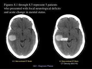
CECT in bovine osteochondral plugs. (A) Representative CECT images of control and degraded samples (exposure to chondroitinase ABC for 8 h and for 30 h) demonstrate an increase in CT attenuation of articular cartilage with increased exposure to chondroitinase ABC. (B) Representative Toludine-blue stained sections indicate a progressive loss of GAG (blue staining) from the ECM as indicated by CECT in (A).
Issues? • Nonspecific bio-distribution, • Relatively small size -tend to undergo rapid renal clearance from the body • High osmolality and/or high viscosity of the contrast media formulations can lead to renal toxicity and adverse physiological effects • High “per dose” concentrations are required • High rates of extravasation and equilibration between intravascular and extravascular compartments at the capillary level --make it difficult to obtain meaningful and clear CT images
Iohexol Containing Polymeric Nanoparticle http://pubs.acs.org/doi/full/10.1021/ja405196f
A Direct Comparison Between Small Molecule and NP Agents Containing Iohexol (A) Serial fluoroscopic images of C57BL/6 mice following jugular vein injection of 200 μL of conventional iodinated contrast agent (iohexol) solution (upper panel) and poly(iohexol) NP solution (lower panel) at 250 mg iohexol/kg, respectively. Images taken at 0 and 60 min after injection were shown. Arrows indicated the enhanced contrast in the bladder regions. (B) In vivo circulation time of poly(iohexol) NP and iohexol. 64Cu-labeled poly(iohexol) NP and iohexol were injected intravenously through the tail vein of mice. At various time points (5, 15, and 30 min and 1, 2, 4, 6, 8, 12, 24, and 48 h), blood was withdrawn intraorbitally, and the radioactivity was measured by the γ-counter to evaluate the systemic circulation of the poly(iohexol) NP (red) and iohexol (blue) (n = 3)
MCF-7 Xenograft Study Serial axial CT images of the MCF-7 tumors in mice following intratumoral injection of 200 μL of iohexol (upper panel) and poly(iohexol) NPs (lower panel) at 50 mg iohexol/kg. Images were taken before injection as well as 5 min, 1 h, and 4 h post injection. Arrows indicate the enhanced contrast regions in the tumor bed. Serial sections of coronal CT images in MCF-7 xenografts bearing mice following the same treatment as described in (A). Arrows indicate the enhanced contrast regions in the bladder. (C) Enhanced density (ΔHU) of tumors at 5 min, 1 h, and 4 h after injection of poly(iohexol) NPs or iohexol.
Metals for CT Contrast Agents Prerequisite features: High payload (>500k metal atoms/NP) High atomic number (Z) Metal with well-positioned K-edge energy Biocompatible surface Defined in vivo characteristics Bio-elimination Stability (shelf life/in-vivo) Coating Homing agent High Z metal Au Gd Yb Bi Z: 79 K-edge: 80.7 keV Pros/Cons + Well studied metal - Cost ($55/g.) - High k-edge Z: 83 K-edge: 90.8 keV Pros/Cons - Not water soluble - High k-edge Z: 70 K-edge: 61.3 keV Pros/Cons + Well placed K-edge + Cost efficient (~$10/g.) Z: 64 K-edge: 50.2 keV Pros/Cons + Well placed K-edge + Cost efficient + (In clinical practice) - Known Safety issues Schirra, Pan et al J. Mater. Chem., 2012, 22, 23071-23077 Pan, Schirra et al ACS Nano. 2012, 6(4):3364-70. Pan et. al. AngewChem Intl Ed. 2010, Ed. 9635-39
K-edge energies and X-ray mass attenuation coefficients for heavy elements used in CT imaging
Stable Xenon-enhanced Contrast CT Uses the inert gas xenon to measure cerebral blood flow (CBF) in various brain regions This technique uses stable non-radioactive 131Xe (At.#54; At. Wt. 131.293) An alternative to SPECT Patient inhales a mixture of xenon and oxygen over the period of a few minutes, allows measurement of their increased in density caused by the gas in brain tissue
Advantages • Can be incorporated into all existing CT technologies . • Can be used to determine local cerebral blood flow in an area as small as 1 x 1 x 5 mm3 area • Can be repeated within 20 mins, allowing the assessment of hemodynamic states including (in certain well-defined settings) • Helps to evaluate acute stroke, occlusive vascular disease, carotid occlusion testing, vasospasm, arteriovenous malformations, and head trauma management
Data are acquired during inhalation of a gas mixture containing 28% 131Xe and oxygen • A radio opaque, highly lipid soluble, diffusible indicator capable of crossing the blood brain barrier. • It provides a measure of tissue perfusion with quantification based on a modification of the Fick’ principle. where CO = Cardiac Output, Ca = Oxygen concentration of arterial blood and Cv = Oxygen concentration of mixed venous blood. and hence calculate cardiac output. Note that (Ca – Cv) is also known as the arteriovenous oxygen difference. VO2, oxygen consumption in ml of pure gaseous oxygen per minute. Ca, the oxygen concentration of blood taken from the pulmonary vein (representing oxygenated blood) Cv, the oxygen concentration of blood from an intravenous cannula (representing deoxygenated blood)
Disadvantages Not FDA approved yet. Approved in the Europe CT based perfusion imaging is considered investigational for all indications including the diagnosis and management of acute cerebral ischemia (stroke). Quantitative CBF studies can be difficult to perform in patients with associated pulmonary pathology since the technique is based on the assumption that the end-tidal xenon concentration is identical to the arterial concentration.
Lymph Node Imaging with Bi2S3 Nanoparticles CT imaging of a lymph node of a mouse with the BPNP imaging agent. a,b, Three-dimensional volume renderings of the CT data set, the length of the reconstruction is 3.8 cm. c, Coronal slice (length of the slice 2.3 cm). d, Transverse slice at the height indicated by the horizontal lines in b. The maximal diameter of the mouse 1.8 cm.
Targeted Bismuth Nanoparticles In vivo micro-CT volume reconstructions post–injection polyethyleneglycol 5000 coated Bi2S3 nanoparticles that do not contain a peptide label. X-ray CT images of tumor-bearing mouse immediately (a), 2 h (b), 4.5 h (c), and 24 (d) after injection of Bi2S3nanoparticles labeled with LyP-1.
Are Hounsfield Units (HU) Energy Dependent? Conventional CT: The HU measurement is a weighted average of the beam absorption over the entire range of beam energies Energy-resolved CT: Multiple narrow sections of the energy spectrum are sampled simultaneously, providing a range of energy-dependent HU across the spectrum. As each material has a specific measurable X-ray spectrum, imaging allows for multiple materials to be quantified and differentiated from each other simultaneously Dual Energy CT: Commercially available dual energy systems measure two materials and some dual energy research machines measure up to three materials.
Interactions of X-ray with matters (i) A portion of X-rays is transmitted without interaction. (ii) The energy of the incident X-ray is absorbed by an atom, and then X-ray with the same energy is emitted with a random direction (Coherent scattering). (iii) When the incident X-ray collides with outer-shell electrons, a portion of the X-ray energy is transferred to the electron, and the X-ray photon is deflected with a reduced energy (Compton scattering). (iv) When the incident X-ray transfers its energy to inner-shell electron, the electron is subsequently ejected, and the vacancy of the electron shell is filled by outer-shell electrons, producing a characteristic X-ray (Photoelectron effect).
Mass attenuation coefficients of several materials as function of X-ray energy Excitation of a 1s electron occurs at the K-edge, while excitation of a 2s or 2p electron occurs at an L-edge (A) Mass attenuation coefficients of a variety of elements. (B) Photon energy distribution generated from the X-ray tube of a CT scanner run at 80 or 140 kV.
Advanced Detector Technology Energy discriminating photon counting detectors Spectral/multi energy CT has the potential to distinguish different materials by K-edge characteristics. K-edge imaging involves the two energy bins on both sides of a K-edge.
Dual Energy CT The Selective Photon Shield ensures dose neutrality by eliminating spectral overlap. This makes Dual Energy as dose-efficient as any single 120 kV scan. • During a Dual Source Dual Energy scan, two CT datasets are acquired simultaneously with different kV and mA levels, allowing to visualize differences in the energy-dependence of the attenuation coefficients of different materials. • These images are combined and analyzed to visualize information about anatomical and pathological structures. http://www.healthcare.siemens.com/computed-tomography/technologies-innovations/ct-dual-energy/technical-specifications
One Basic Reason for Use of Dual Energy CT: Material Differentiation • By scanning a patient at two different energy spectra (e.g. at 56 kV and 76 kV), the attenuation difference of the same material is different. • Iodine has higher attenuation difference, compared to bone. • Scanning allows the computer to process bone and iodine content on images differently. • Routine Use of Dual-energy CT for Material Differentiation • Creation of 3D vascular images ("Direct Angio") by easy removal of bony structures • Plaque analysis (calcified vs. soft plaques) • Lung perfusion • Virtual unenhanced scan (creation of unenhanced scan from enhanced images by deleting iodine content from the images) • Calculi characterization (uric acid vs. others)
Dual Energy in Angiography Use the spectral properties of iodine to differentiate it from other dense materials in the dataset (similar to magnetic resonance angiography (MRA)). With Dual Energy CT, it is possible to identify bone by its spectral behavior and to erase it from an angiogram. Then, the iodine in the vessels remains the only dense material in the dataset and a MIP can be calculated from a CT angiogram to closely resemble an MRA. Additionally, it is possible to detect those voxels that contain both calcium and iodine and add them back to the dataset. Calcified plaques of atherosclerotic vessels can thereby be switched on and off in the dataset to visualize both the residual lumen and the plaque distribution. http://www.dsct.com/index.php/clinical-applications-dual-energy-ct/
Differentiation of Tendons and Ligaments Tendons and ligaments have weak spectral properties, presumably due to the densely packed collagen. It is possible to identify thick tendons and ligaments in Dual Energy CT datasets and to display them separately, for example, to visualize the tendons of the wrist and identify ruptures. However, signal-to-noise ratio is not sufficient to depict thin ligaments; thus the clinical value of this application is limited.
Coronary Thrombus Imaging by Spectral CT Nanobeacons target fibrin of thrombus on ruptured plaque • Nanobeacons (Au, Bi,…) bind to fibrin • Conventional CT is unable to selectively image materials • Spectral CT enables material specific imaging of suitable metals • New Nanobeacons and advances in statistical image reconstruction methods improve coronary fibrin imaging Fibrin Ca deposit Plaque formation non-separated attenuation from nanoparticle and Ca Selective imaging of nanoparticles
Quantitative Tissue Differentiation Targeted bismuth nanocolloids distinguishes fibrin microdeposits from calcium Hospitaltour.com Specimen removal Human Coronary phantom Spectral CT image of a fibrin clot phantom with embedded calcium chloride (white arrow) targeted (green arrow) in a glass tube (blue arrows denote wall). Carotid Enderectamy Specimen Calciumred& Bismuth Gold) Soft tissue invisible due to low X-ray attenuation Local Bi-conc ~0.1 g/cm3 Ca-separated Pan et. al. AngewChemInt Ed. 9635-9639 (2010)
Targeting in situ Clots (Thrombus) in Rabbits
(A) Structure of Au–high-density lipoprotein (HDL), a macrophage targeted CT contrast agent. (B) Negative stain transmission electron microscopy characterization of the nanoparticle. (C) Spectral CT image of an artery phantom. (D) Spectral CT image of an atherosclerotic mouse acquired 24 h after injection with Au–HDL and directly after injection of an iodine nanoemulsion. In (C) and (D) gold (yellow), iodine (red) and photoelectric (blue) images are overlaid on a Compton image (grayscale).