Download
1 / 17
170 likes | 175 Views
This article explores the use of 3-D hybrid pixel detectors in particle trackers, discussing the choice of sensors, dedicated electronic chips, and bump-bonding solder for interconnection. It also highlights the applications of these detectors in ATLAS/LHC and their potential for upgrades in SLHC.

E N D
The 3-D IT: The new challenge for ATLAS Pixel detectors CPPM Marseille (France): B. Chantepie, J.-C. Clémens, R. Fei, D. Fougeron, S. Godiot, P. Pangaud, A. Rozanov Bonn University (Germany): D. Arutinov, M. Barbero, T. Hemperek, M. Karagounis, H. Krüger, A. Kruth, N. Wermes. LBNL Berkeley (USA): J. Fleury, M. Garcia-Sciveres, A. Mekkaoui
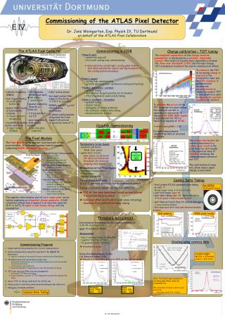
Hybrid Pixel Detectors for particles trackers • An early 3-D approach!! • Choice of several sensors for particles detection (HR Si, diamant,3D..) • Dedicated electronic chip AND • A bump-bonding solder for interconnection • Sensors for ionizing particles (e-, photon, gamma, etc ..) • Electronic pixel readout • Monolithic device • Analog detection (low noise, low power) • Digital readout
Hybrid Pixels Detector of ATLAS/LHC • Like a big camera with a 1.5 m2 area and 80 Million of Pixels with a snapshot every 25ns • Hybrid Pixels Detector of ATLAS/SLHC • More luminosity, more pixels more ionizing particles, more … !!! • LHC : Luminosity of 1034 cm-2.s-1 • SLHC expected 10 times more !!! ATLAS Pixel Detectors for LHC/SLHC
Tezzaron-Chartered 3D MPW : ATLAS/SLHC sub-part ATLAS/SLHC C and D Sub-part LBL G Sub-part G1 G2
SEU-3D SEU-3D FETC4-AE FETC4-DS TSV Daisy Chain + BI Electrical Test TSV vs Transistors + capacitors Electrical Test TSV vs Transistors Mechanical stress DFF + Trans + Cap Fermilab 3-D Multi-Project Run : C-Band ATLAS • FETC4-AE (CPPM) : same than FEI4_Proto1, but in Chartered 0.13LP • FETC4-DS (CPPM) : Shift Register + counter + readout data and ”Drum registers“ • SEU-3D (CPPM) : SEUless memories blocks • General test structures (CPPM) : TSV + BI Daisy chain (electrical parameters) ; TSV capacitors value with and without BackMetal and BI ; Transistors (Linear and ELT) closed to TSV ; Mechanical stress effects of devices (Trans, Cap, Res, DFF)
OmegaPix Digital OmegaPix Analog FETC4-AE FETC4-DC Electrical Test TSV vs Transistors TSV, Cap and Bump Electrical Test TSV vs Transistors Fermilab 3-D Multi-Project Run : D-Band ATLAS • FETC4-AE (CPPM) : same than FEI4_Proto1, but in Chartered 0.13LP • FETC4-DC (Bonn-CPPM) : Digital pixels Read-out "à la FEI4“ (M.Barbero) • OmegaPix (LAL) : see (D. Thienpont ) presentation • General test structures (CPPM) : TSV + BI Daisy chain (electrical parameters) ; TSV capacitors value with and without BackMetal and BI ; Transistors (Linear and ELT) closed to TSV ; Mechanical stress effects of devices (Trans, Cap, Res, DFF)
FETC4-AH FETC4-DS Fermilab 3-D Multi-Project Run : G-Band LBNL- Fermilab • FETC4-AH (LBL-CPPM) : same than FEI4_Proto1 but with holes collection. • FETC4-DS (CPPM) : Shift Register + counter + readout data and ”Drum registers“
ATLAS 3D Read-Out chip Pixel size : 50 x 125 µm Pixel array size : 160 x 336 Chip size : 19 x 20 mm FETC4 - Atlas 3-D Read-Out chip Fermilab proposal 3D HEP consortium Tezzaron-Chartered MPW FETC4-AEDS FETC4-AEDC Tezzaron Chartered 1st MPW Run (Summer 2009) Chartered 1st Prototype (Feb 2009) FEC4-P1 Chartered 2nd Prototype (Nov 2009) FEC4-P2 FETC4-A Chartered 3rd Prototype (June 2010) FEC4-P3 Tezzaron Chartered 2nd MPW Run (?)
sensor Back Side Metal SuperContact Tier 1 (thinned wafer) M1 M2 M3 M4 M5 M6 Bond Interface M6 M5 M4 M3 M2 M1 Tier 2 SuperContact FETC4_AEDS (DC) : Atlas 3-D Read-Out proto chip 2 Tiers + Sensor • Analog part : Tier 1 (C1, D1) thinned to use SuperContact which are connected to the Back side metal (wire and bump-bonding interface) • Digital part : Tier 2 (C2, D2). • Sensor : Tier 0
Sensor layout : Max-Planck-Institut für Physik, Werner Heisenberg Institut , Munich Bump-Bonding : IZM , Munich FETC4_AEDS (DC) : Atlas 3-D Read-Out proto chip Sensor aspect Due to the bonding constraints, the geometrical sensor area had to be shrink • Sensor : 7 columns of 48 pixels • Tier 1 and Tier 2 : 14 columns of 61 pixels
Tezzaron-Chartered 3D MPW (C1 and D1) : Analog Tier FETC4-AE Based from the FEI4-P1 chip made in IBM 0.13µm technology : Signal from Sensor, via TSVs 2 ways for read-out the discriminator: • By the classical way in Tier1 • By the FEC4-DS or DC chip (Tier 2) via the BI.
3 functions : Read-out the analog Tier 1 Noise generator (pick-up, coupling, etc…) in front of 11 specifics area of Tier 1 (preamplifier, feed-back capacitor, DAC…) Several programmable shielding configuration Analog tier and Digital tiers are face-to-face with only ~5µm of distance FE-TC4-DS is mainly dedicated to study the parasitic coupling between two tiers ANALOGUE DIGITAL Tezzaron-Chartered 3D MPW (C2) : Digital Tier FETC4-DS
FEC4-P1, run 2D(submission February 2009, test April 2009) : 2D run in 0.13LP Chartered technology. 1st approach Layout translation of FEI4-P1 IBM 0.13µm 8LM to FEC4-P1 CHRT 0.13µm 8LM FETC4-AEDS (DC) (submission July 2009, test expecting before summer 2010) : 3D run in 0.13LP Tezzaron-Chartered technology. Layout translation of FEI4-P1 IBM 0.13µm 8LM to FETC4-P1 CHRT 0.13µm 5LM Move from de 8LM to 5LM 3D structures Two additional Digitals Tiers ATLAS chips - historical review :FEC4-P1 and FETC4-AEDS(DC)
Test Results of FEC4-P1 : Chip is working The minimum threshold is # 1100 e- ; threshold resolution# 200 e-; Noise < 80 e- Irradiation : the chip is working for a X-rays dose rate up to 200MRad Defected has been found for an protons dose-rate up to 160 MRad. The memories structures (Latches) stacked up to 1. FEC4-P2, run 2D (submission November 2009, chip under test) : 2D run in 0.13LP Chartered technology. 2nd prototype to corrected the first one. Analog Part : Optimization of the transistors size dedicated to the Chartered constraints technology Digital Part : Memories latches => modification with 2 kinds of architecture. Layout optimization. ATLAS chips - historical review : FEC4-P1 et FEC4-P2
FEC4-P3, run 2D (submission June 2010) : 2D run in 0.13LP Chartered technology. Hope last prototype . To finished the translation of the last building blocks in CHRT technology : Current Ref, PLL, LVDS, etc … Pixel modification : to shrink pixel size to 125µm and to reduce the metal levels to 5. Structures ready for the 3D chip FETC4-A, run 3D (before the end of 2010) : Very large matrix size : 336 x 80 Small pixel size : 125µm x 50µm Twin of FEI4-A but with an half size pixel. FEx4 ATLAS chips : next in 2010…
Feedback of 3D development • 3D vision • Long understanding 3D Tezzaron process • Bad layer numbers definition • 2 TopMetal but 1 TM for BI !!! • Backside Metal : poor rules!! • Filling!! And floating metal !! • PDK • Chartered PDK is not really a PDK but pieces of PDK • Very poor PDK with not optimized PCELLS regarding min values of rules !!! • Chartered PDK is not stable and need to be wary all the time (no support but only access to GlobalFoundries site!!) Ever requested, never replied !!! • Sub-versions of Calibre files are not compatible between us (bad experience with FEC4_P1) • Home-made 3D DRC-LVS calibre deck tools • Check face to face BI connections • Check TSV density • Bad layers definitions, source of mistakes • Developed our own StreamLayers file • Now we switched to the Cadence OA version Request Only one PDK up-to-date, from one source, with one support team, and contact persons