Download
1 / 14
140 likes | 145 Views
Learn how to calculate average power, reactive power, apparent power, and power factor for a Y-connected balanced load. Explore the three-wattmeter method and two-wattmeter method for power measurement.

E N D
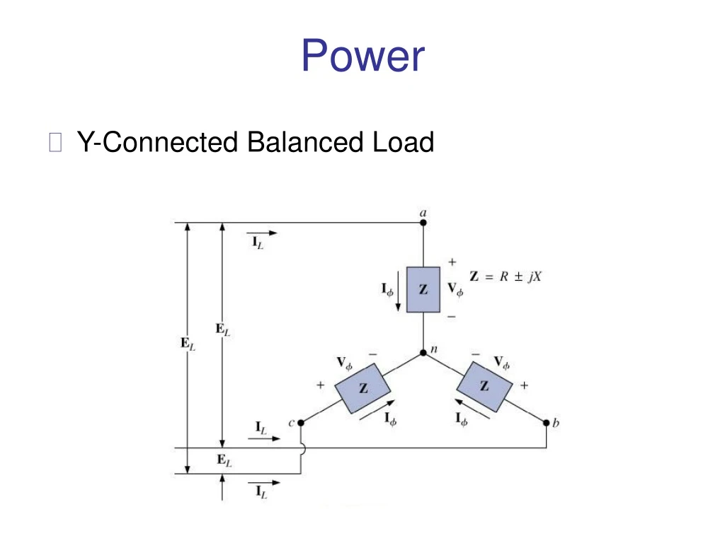
Power • Y-Connected Balanced Load
Power • Average Power • The average power delivered to each phase • Total power to the balanced load is • Reactive Power • The reactive power of each phase (in volt-amperes reactive) is • The total reactive power of the load is
Power • Apparent Power • The apparent power of each phase is • The total apparent power of the load is • Power Factor • The power factor of the system is
Power • ∆-Connected Balanced Load
Power • Average Power • Reactive Power
Power • Apparent Power • Power Factor
Three-Wattmeter Method • The power delivered to a balanced or an unbalanced four-wire, Y-connected load can be found by the three-wattmeter method. • Each wattmeter measures the power delivered to each phase. • The potential coil of each wattmeter is connected parallel with the load, while the current coil is in series with the load.
Three-Wattmeter Method • For the - connected load (balanced or unbalanced), the wattmeters are connected as shown. • The total power is again the sum of the three.
Two-Wattmeter Method • The power delivered to a three-phase, three-wired, ∆- or Y-connected, balanced or unbalanced load can be found using only two wattmeters if the proper connection is employed and if the wattmeter readings are interpreted properly.
Two-Wattmeter Method • The total power delivered to the load is the algebraic sum of the two wattmeter readings. • In the first method we find the (leading or lagging) of any one phase of the load. • We use this information and apply it directly to the curve.
Two-Wattmeter Method • The second method for determining whether the total power is the sum or difference of the two wattmeter readings involves a simple laboratory test. • For the test to be applied, both wattmeters must first have an up-scale deflection. • If one of the wattmeters has a below-zero indication, an up-scale deflection can be obtained by simply reversing the leads of the current coil of the wattmeter.
Two-Wattmeter Method • To perform the test: • Take notice of which line does not have a current coil sensing the line current. • For the lower-reading wattmeter, disconnect the lead of the potential coil connected to the line without the current coil. • Take the disconnected lead of the lower-reading wattmeter’s potential coil, and touch a connection point on the line that has the current coil of the higher-reading wattmeter. • If the pointer deflects downward (below zero watts), the wattage reading of the lower-reading wattmeter should be subtracted form that of the higher-reading wattmeter. Otherwise, the readings should be added.
Unbalanced, Three-Phase, Four-Wire, Y-Connected Load • For the three-phase, four-wire, Y-connected load, if conditions are such that none of the load impedances are equal. • We have an unbalanced polyphase load • Neutral is a common point between the load and source, so the voltage across each phase voltage of the generator: • The current in the neutral for any unbalanced system, at point n:
Unbalanced, Three-Phase, Three-Wire, Y-Connected Load • The required equations can be derived by applying Kirchhoff’s voltage law around each closed loop.