Download
1 / 20
200 likes | 516 Views
ARM Instructions II. Prof. Taeweon Suh Computer Science Education Korea University. Data Processing Instructions. Arithmetic instructions Logical instructions Comparison instructions Move instructions. Arithmetic Instructions – ADC.

E N D
ARM Instructions II Prof. Taeweon Suh Computer Science Education Korea University
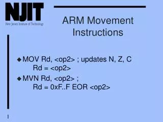
Data Processing Instructions • Arithmetic instructions • Logical instructions • Comparison instructions • Move instructions
Arithmetic Instructions – ADC • ADC adds two operands with a carry bit, placing the result in Rd • It uses a carry bit, so can add numbers larger than 32 bits • Use S suffix to update conditional field <64-bit addition> 64 bit 1st operand: R4 and R5 64 bit 2nd operand: R8 and R9 64 bit result: R0 and R1 ADDS R0, R4, R8 ; R0 = R4 + R8 and set carry accordingly ADCS R1, R5, R9 ; R1 = R5 + R9 + (Carry flag)
Arithmetic Instructions – SBC • SBC subtracts operand 2 from operand 1 with the carry flag, placing the result in Rd • It uses a carry bit, so can subtract numbers larger than 32 bits. • Use S suffix to update conditional field <64-bit Subtraction> 64 bit 1st operand: R4 and R5 64 bit 2nd operand: R8 and R9 64 bit result: R0 and R1 SUBS R0, R4, R8 ; R0 = R4 – R8 SBC R1, R5, R9 ; R1 = R5 – R9 - !(carry flag)
Examples Before: Before: Before: r0 = 0x0000_0000 r1 = 0x0000_0005 ADD r0, r1, r1, LSL#1 r0 = 0x0000_0000 r1 = 0x0000_0002 r2 = 0x0000_0001 SUB r0, r1, r2 r0 = 0x0000_0000 r1 = 0x0000_0077 RSB r0, r1, #0 // r0 = 0x0 – r1 After: After: After: r0 = 0x0000_0001 r1 = 0x0000_0002 r2 = 0x0000_0001 r0 = 0xFFFF_FF89 r1 = 0x0000_0077 r0 = 0x0000_000F r1 = 0x0000_0005
Examples • Why is the C flag set (C = 1)? cpsr = nzcv r1 = 0x0000_0001 SUBS r1, r1, #1 Before: cpsr = nZCv r1 = 0x0000_0000 After:
Logical Instructions Rn Rm Syntax: <instruction>{cond}{S} Rd, Rn, N Barrel Shifter N ALU Rd
Comparison Instructions – CMN • CMN compares one value with the 2’s complement of a second value • It performs a comparison by adding the 2nd operand to the first operand • It is equivalent to subtracting the negative of the 2nd operand from the 1st operand • Note that there is no destination register • It only update cpsr flags based on the execution result CMN R0, R1;
Comparison Instructions – TST • TST tests bits of two 32-bit values by logically ANDing the two operands • Note that there is no destination register • It only update cpsr flags based on the execution result • TEQ sets flags by EORing the two operands
Examples cpsr = nzcv r0 = 4 r9 = 4 CMP r0, r9 Before: cpsr = nZCv r0 = 4 r9 = 4 After:
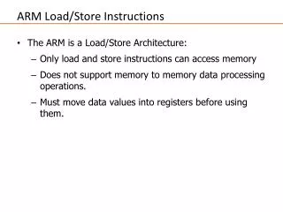
Memory Access Instructions • Load-Store (memory access) instructions transfer data between memory and CPU registers • Single-register transfer • Multiple-register transfer • Swap instruction
Multiple Register Transfer – LDM, STM Syntax: <LDM/STM>{cond}<addressing mode> Rn{!}, <registers>^
Multiple Register Transfer – LDM, STM • LDM (Load Multiple) loads general-purpose registers from sequential memory locations • STM (Store Multiple) stores general-purpose registers to sequential memory locations
LDM, STM - Multiple Data Transfer • In multiple data transfer, the register list is given in a curly brackets {} • It doesn’t matter which order you specify the registers in • They are stored from lowest to highest • A useful shorthand is “-” • It specifies the beginning and end of registers STMFD R13!, {R0, R1} // R13 is updated LDMFD R13!, {R1, R0} // R13 is updated STMFD R13!, {R0-R12} // R13 is updated appropriately LDMFD R13!, {R0-R12} // R13 is updated appropriately
Examples LDMIA r0!, {r1-r3} After: Before: Mem32[0x80018] = 0x3 Mem32[0x80014] = 0x2 Mem32[0x80010] = 0x1 r0 = 0x0008_0010 r1 = 0x0000_0000 r2 = 0x0000_0000 r3 = 0x0000_0000 Mem32[0x80018] = 0x3 Mem32[0x80014] = 0x2 Mem32[0x80010] = 0x1 r0 = 0x0008_001C r1 = 0x0000_0001 r2 = 0x0000_0002 r3 = 0x0000_0003
Stack Operation • Multiple data transfer instructions (LDM and STM) are used to load and store multiple words of data from/to main memory • IA: Increment After • IB: Increment Before • DA: Decrement After • DB: Decrement Before • FA: Full Ascending (in stack) • FD: Full Descending (in stack) • EA: Empty Ascending (in stack) • ED: Empty Descending (in stack) ARM default stack
(Assembly) Language • There is no golden way to learn language • You got to use and practice to get used to it