Download
1 / 26
280 likes | 455 Views
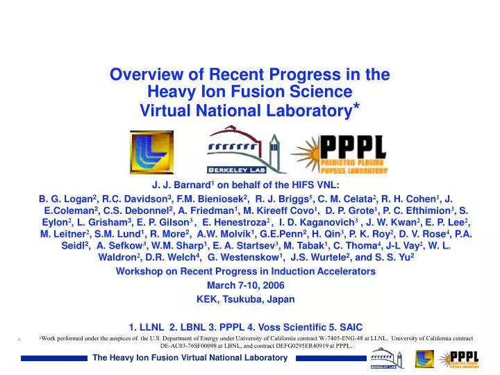
Overview of Recent Progress in the Heavy Ion Fusion Science Virtual National Laboratory *. J. J. Barnard 1 on behalf of the HIFS VNL:

E N D
Overview of Recent Progress in the Heavy Ion Fusion Science Virtual National Laboratory* J. J. Barnard1on behalf of the HIFS VNL: B. G. Logan2, R.C. Davidson3, F.M. Bieniosek2, R. J. Briggs5, C. M. Celata2, R. H. Cohen1, J. E.Coleman2, C.S. Debonnel2, A. Friedman1, M. Kireeff Covo1, D. P. Grote1, P. C. Efthimion3, S. Eylon2, L. Grisham3, E. P. Gilson3 , E. Henestroza2 , I. D. Kaganovich3 , J. W. Kwan2, E. P. Lee2, M. Leitner2, S.M. Lund1, R. More2, A.W. Molvik1, G.E.Penn2, H. Qin3, P. K. Roy2, D. V. Rose4, P.A. Seidl2, A. Sefkow3, W.M. Sharp1, E. A. Startsev3, M. Tabak1, C. Thoma4, J-L Vay2, W. L. Waldron2, D.R. Welch4, G. Westenskow1, J.S. Wurtele2, and S. S. Yu2 Workshop on Recent Progress in Induction Accelerators March 7-10, 2006 KEK, Tsukuba, Japan 1. LLNL 2. LBNL 3. PPPL 4. Voss Scientific 5. SAIC *Work performed under the auspices of the U.S. Department of Energy under University of California contract W-7405-ENG-48 at LLNL, University of California contract DE-AC03-76SF00098 at LBNL, and contract DEFG0295ER40919 at PPPL.
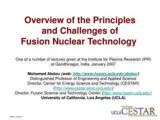
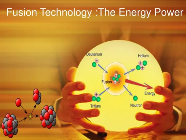
The goal of the HIFS-VNL is to investigate the beam science common to both High Energy Density Physics (HEDP) and fusion The program concentrates on ion beam experiments, theory and simulations to address a top-level scientific question central to both HEDP and fusion: How can heavy ion beams be compressed to the high intensities required for creating high energy density matter and fusion? Principal science thrust areas: - High brightness beam transport - Focusing onto targets - Longitudinal beam compression - Advanced theory and simulation tools - Beam-target interaction and warm dense matter physics
Outline of Presentation • The HEDP/Warm Dense Matter mission for the HIFS VNL • - Bragg peak heating • Neutralized Focusing and Drift Compression Experiments • Neutralized focusing • Neutralized longitudinal beam compression • Pulse Line Ion Accelerator (PLIA) • Novel slow-wave accelerator for producing intense high-current ion beams. • High Brightness Beam Transport • Electron cloud • Beam stability • Multi-beamlet injector • Future: Warm Dense Matter and NDCX-II • Other VNL talks: R. Briggs - PLIA (Tuesday) • G. Westenskow - Multibeamlet Injector (Wednesday) • S. Lund - Space charge transport limits (Wednesday) • H. Qin - Time dependent envelope equation (Thursday)
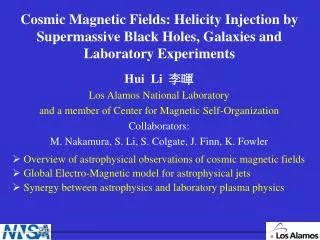
The r - T regime accessible by beam-driven experiments is similar to the interiors of giant planets and low-mass stars Figure adapted from “Frontiers in HEDP: the X-Games of Contemporary Science:” Accessible region using Intense beams Region is part of Warm Dense Matter (WDM) regime WDM lies at crossroads of: degenerate /classical and strongly coupled/ weakly coupled Terrestial planet See http://hifweb.lbl.gov/public/AcceleraorWDM/TableOfContents.html for talks from 2006 Workshop
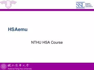
Warm Dense Matter Science requires short intense beam pulse (~ ns). Strategy: placing center of foil at Bragg peak, maximizes uniformity In simplest example, target is a foil of solid or “foam” metal fractional energy loss can be high and uniformity also high if operate at Bragg peak (Larry Grisham, PPPL) Ion beam Example: Ne Energy loss rate DdE/dX DT In example, Eentrance=1.0 MeV/amu Epeak= 0.6 MeV/amu Eexit = 0.4 MeV/amu (DdE/dX)/(dE/dX)≈0.05 (MeV/mg cm2) Enter foil Exit foil (dEdX figure from L.C Northcliffe and R.F.Schilling, Nuclear Data Tables, A7, 233 (1970)) Energy/Ion mass (MeV/amu)
Various ion masses and energies have been considered for Bragg-peak heating Beam parameters needed to create a 10 eV plasma in 10% solid aluminum foam, for various ions (10 eV is equivalent to ~ 1011 J/m3 in 10% solid aluminum) As ion mass increases, so does ion energy and accelerator cost As ion mass increases, current increases, increasing need for neutralization
LSP-PIC simulations demonstrate the possibility of large compression and focusing of charge neutralized ion beamsinside a plasma column (Welch et al., 2004) Snapshots of a beam ion bunch at different times shown superimposed Background plasma @ 10x beam density (not shown) • Ramped 220-390 keV K+ ion beam injected into a 1.4-m -long plasma column: • Axial compression 120 X. • Radial compression to 1/e focal spot radius < 1 mm. • Beam intensity on target increases by 50,000 X. cm Initial bunch length cm 3.9T solenoid focuses beam • Velocity chirp amplifies beam power analogous to frequency chirp in CPA lasers. • Solenoids and/or adiabatic plasma lens can focus compressed bunches in plasma. • Instabilities may be controlled with np>>nb, and Bz field [ Welch, Rose (MRC); Kaganovich (PPPL)].
NDCX-I: A series of experiments towards HEDP (NDCX-II) We have equipment in hand for all NDCX-1 experiments except NDCX-1c Interchangeable (First expts: Neutralized focusing, NTX) Interchangeable
Neutralized Transport Experiment investigated physics of neutralized focusing Volumetric plasma from photoionization ("target plasma" F F D D “Plasma plug” neutralization x and y envelopes (schematically depicted) Non-neutralized 300 keV K+ ions at 25 mA FWHM=1.5 mm FWHM=2.2 mm FWHM=6.6 mm 2004
Measurement Theory 100% neutralized 100% neutralized MEVVA and RF MEVVA and RF MEVVA ONLY MEVVA ONLY Measurements on the Neutralized Transport Experiment (NTX) demonstrate achievement of smaller transverse spot size using volumetric plasma Neither plasma plug nor volumetric plasma. Plasma plug. Plasma plug and volumetric plasma. FWHM = 2.7 cm FWHM = 2.14 mm
Neutralized drift compression experiment (NDCX)- 300 keV K+ ions at 25 mA Tiltcore waveform
60 50 Intensity (au) 40 Compression ratio 30 20 10 100 0 Time (ns) 50 Fold Beam compression achieved in neutralized drift compression experiment Phototube Optical data Corroborating data from Faraday cup LSP simulation Time (ns) 100 0 P.K. Roy et al, PRL, 95, 234801, 2 Dec. 2005
Accel-decel injector with “load-and-fire” column Pulsed resistive column Broadband Pulse Line Ion Accelerator Energy ramping Neutralized Drift Compression Vs(t) from Pulse Forming Network Resistively graded column Insulator column C L Short ion pulse Our first HEDP workshop (October, 2004) included a new accelerator concept: a Pulse Line Ion Accelerator (PLIA) for potential applications to HEDP and IFE • Pulse Line Ion Accelerator is based on slow-wave structures (helices) • Beam “surfs” on traveling pulse of Ez • Ez (helix) >> Ez (space charge) Continuous purging of electrons! December 2005, demonstrated energy extraction from traveling wave Solenoid provides transverse beam confinement Dielectric-filled coax Vz(z,t) ttt vacuum Traveling wave
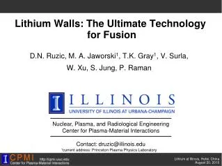
In a Pulse Line Ion Accelerator (PLIA), the accelerating fields are those of a “distributed transmission line” NDCX-II Accelerator Cell Solenoid & cryostat *R.J. Briggs, et al. - LBNL Patent, Aug 2004 Helical winding Output end Input end Compact transformer coupling (5:1 step-up) Input
NDCX-I: A series of experiments towards HEDP (NDCX-II) We have equipment in hand for all NDCX-1 experiments except NDCX-1c Interchangeable (First expts: Neutralized focusing, NTX) Interchangeable
e- e- e- e- e- e- e- e- e- e- e- e- e- quad e- e- e- e- e- e- e- e- e- e- e- e- e- beam = ion Positive Beam e- = electron High-brightness beam transport - electron effects on intense ion beams Electron cloud caused by: Synchrotron radiation Secondary emission from e- accelerated by beam Beam halo scraping e- emission Ionization of background gas especially Expelled ions hitting vacuum wall for HIF, Ionization of desorbed gas HEDP e- motion in a quad Goal:Advance understanding of the physical processes leading to the accumulation of electrons in magnetic quadrupoles in the HCX
In-bore diag. K+ beam Intercepting diagnostics Intercepting diagnostics Also e- coeff.; gas desorption coeff. (GESD) Suppressor Clearing electrodes The High Current Experiment (HCX) is exploring beam transport limits Focus of Gas/Electron Experiments K+ Beam Parameters I = 0.2 (- 0.5) Amp 1 (- 1.7) MeV, 4.5 ms 2 MV INJECTOR MATCHING SECTION ELECTROSTATIC QUADRUPOLES MAGNETIC QUADRUPOLES 4 magnetic quadrupoles; many diagnostics
(b) (c) (a) e- Suppressor on Suppressor off 0V 0V 0V V=-10kV, 0V experiment simulation Comparison: Clearing electrodes and e-suppressor on/off e-supp 200mA K+ • Beam ions • Electrons from ions hitting surface • Secondary electrons Comparison suggests semi-quantitative agreement.
Non-neutralized space charge physics is also being explored in HIFS-VNL: New theoretical explanation of an unanswered question Limit:s0 >~ 85 degrees/period (large emittance growth and particle loss) Explanation: Higher order resonances between particle orbit and matched beam envelope external to the beam core (but near the edge) allow near-edge particles to rapidly increase in oscillation amplitude Core-particle criterion based on this effect reproduces the observed stability boundary PIC simulations confirm core-particle calculations Empirical limit (Tiefenback, 1986) Min Stability boundary derived from core-particle model [Space-Charge Strength] Max [Applied Focus Strength] Details will be presented in this workshop and in: S. Lund and S. Chawla, Nuc. Instr. Meth. A (2006), in press.
7.5 x(mm) -7.5 0.5 1.0 0. 1.5 z (m) Merging beamlet injector experiments on STS-500 validated the concept of this compact, high current source • Monolithic solid sources suffer from poor scaling vs. size at high currents • This new concept circumvents the problem via use of many small, low-current sources Simulation Experiment From a full-gradient (parallel-beamlet) experiment y (m) -0.05 x (m) 0.05 -0.05 x (m) 0.05 • From scaled merging experiment: • Obtained emittances comparable to simulation • Effects of “dirty” physics (electrons, charge exchange) were minimal • Scales to 0.5 A, 1.6 MeV, ~1 -mm-mrad, 13 mA/cm2
Future goal: a user facility for ion beam driven HEDP will have unique characteristics Precise control of energy deposition Uniformity of energy deposition Large sample sizes compared to diagnostic resolution volumes Ability to heat variety of targets (insulators and conductors) Relatively long times allow equilibrium conditions A benign environment for diagnostics High shot rates (10/hour to 1/second) (simple targets and high accelerator rep rates
The experiments in the NDC sequence lead to a user facility (IB-HEDPX) Existing machine, 1 year goal 3 - 5 year goal 10 year goal IB-HEDPX NDCX = neutralized drift compression experiment IB-HEDPX = integrated beam-high energy density physics experiment
NDCX-II Plan: Pulse Line Ion Accelerator- a unique, more capable accelerator for ion-driven HEDP is being evaluated Neutralized Compression Final Focus Solenoid Focusing Helix Acceleration Short Pulse Injector 1 eV target heating >0.1 mC of Na+ @ 24 MeV heating @ Bragg peak dE/dx NDCX-1C + $5M hardware
0.1 solid Al 0.01 solid Al (at t=2 ns) Hydra simulations confirm temperature uniformity of targets at 0.1 and 0.01 times solid density of aluminum (20 MeV Ne+ ions at 330 A) 0 Dz = 48 m r =1 mm 0.7 1.0 Axis of symmetry 1.2 2.0 t(ns) 2.2 Dz = 480 m
New theoretical EOS work meshes very well with the experimental capabilities we will be creating R. Lee plot of contours of fractional pressure difference for two common EOS R. More: Large uncertainties in WDM region arise in the two phase (liquid-vapor) region Accurate results in two-phase regime essential for WDM R. More has recently developed new high-quality EOS for Sn. Interesting behavior in the T~1.0 eV regime. P (J/cm3) Critical point unknown for many metals, such as Sn r (g/cm3) T (eV) EOS tools for this temperature and density range are just now being developed.
Conclusions • There have been many scientific advances by the HIFS VNL during the past two years: - Demonstration of compression and focusing of ultra-short ion pulses in neutralizing plasma background. - New computational, theoretical and experimental results in high brightness beam research, including electron cloud effects - New accelerator concept: Pulse Line Ion Accelerator. - Completion of a multibeamlet injector for heavy ion fusion drivers - Development of a concept and path to Warm Dense Matter investigations • Heavy ion research is of fundamental importance to both HEDP in the near term and to fusion in the longer term. • Experiments heavily leverage existing equipment and are modest in cost. • Theory and modeling play a key role in guiding and interpreting experiments.