Download
1 / 57
580 likes | 691 Views
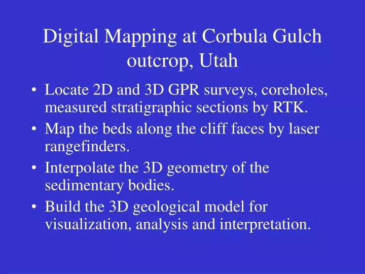
Digital Mapping at Corbula Gulch outcrop, Utah. Locate 2D and 3D GPR surveys, coreholes, measured stratigraphic sections by RTK. Map the beds along the cliff faces by laser rangefinders. Interpolate the 3D geometry of the sedimentary bodies.

E N D
Digital Mapping at Corbula Gulch outcrop, Utah • Locate 2D and 3D GPR surveys, coreholes, measured stratigraphic sections by RTK. • Map the beds along the cliff faces by laser rangefinders. • Interpolate the 3D geometry of the sedimentary bodies. • Build the 3D geological model for visualization, analysis and interpretation.
Photomosaic of Cliff face W E S N
3D Perspective View of Survey data Layout
3D Perspective View of Survey data Layout
GPR Cubes and Profiles (from Corbeanu, 2000)
3D Perspective View of Survey data Layout
The high-resolution topographic model at the southeast corner of the outcrop
Photomosaic of Cliff face W E S N
Conclusions • Utilize GPS and laser sketching to locate the GPR survey lines, stratigraphic sections, coreholes, and sedimentary bounding surfaces. • These digital data enable us to quantitatively analyze the key surfaces. • A three-dimensional geological model was interpolated with these digital data and 4 coreholes.
Conclusions (continuing) • The results of this project demonstrates the usefulness of digital surface mapping and power of integration of digital subsurface information. • The final GPR analysis and interpretation can utilize these interpolated surface fits. • The final three-dimensional model will incorporate all of subsurface and surface geology.
3-D GPR RESOLUTION GPR vertical resolution = 0.5 m Seismic vertical resolution = 15 m
FERRON SANDSTONE LOCATION • Sequence stratigraphic framework well established • Reservoir analog for oil fields in Gulf of Mexico and North Sea • Good exposure of the vertical cliff faces • Flat mesas and an arid environment are ideal for GPR surveying Y Delta shoreline Corbula Gulch Coyote Basin X
v = c/ k, where c is the velocity of light in a vacuum GPR METHOD • High resolution electro-magnetic method • Similar to seismic methods • Characterizes a medium by its electrical permittivity, k and electrical conductivity, s. • Decreasing velocity with depth • Depth of penetration proportional to the loss tangent System console Antennas Optic fiber tan(d) = s/e0wk, where : e0 = permittivity in a vacuum w = angular frequency
CORBULA GULCH BASEMAP • reservoir simulator voxel scale: 3-D GPR cubes • (51m x 28m and 31m x 27) • reservoir grid cell scale • (100mx100m) • inter-well scale • (550mx350m)
INTEGRATING OUTCROP AND GPR DATA • Good correlation of lithology and permeability. • Good correlation of lithology and velocity. • GPR reflections are produced at the surface between layers with contrast in electrical properties.
3-D GPR INTERPRETATION • High amplitude, continuous, oblique GPR reflections. • Tuning effects at thin layers interfaces resolved with GPR attributes.
CONCLUSION • To effectively integrate geologic and GPR data, 3-D migration of the GPR data from the time domain into the depth domain is essential. • Correlating outcrop, boreholes and GPR data allows relationships between vertical facies successions through different architectural elements and their lateral geometry to be directly interpreted in 3-D. • The channel deposits at Coyote Basin are interpreted as scour and fill channel deposits of distributary channels on the upper delta plain.
CONCLUSION • Reservoir heterogeneities are estimated by modeling 3-D experimental variograms of GPR amplitudes and are smaller (4-6 m) in scour and fill channel deposits and longer (10-15 m) in marine influenced point bar deposits. • 3-D permeability and mudstone distributions can be predicted from empirical relationships between physical properties and GPR attributes.
Objectives • 3D integration of data sets, including GPR surfaces, borehole and cliff face data. • Building 3D model for visualization, analysis and interpretation.
Data Source • GPR Survey • Cliff Face Laser Mapping • Stratigraphic Measured Sections • Well cores -All Integrated by GPS
Photomosaics of Cliff Faces W E S N
3D Perspective View of Survey Data Layout
Rendering Procedures • Curve fitting of the data • Generating initial surfaces • Installing constraints to honor geologic interpretations.
Incline 4 with laser data Laser data