Download
1 / 10
210 likes | 586 Views
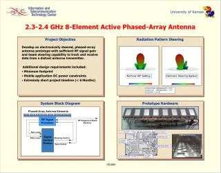
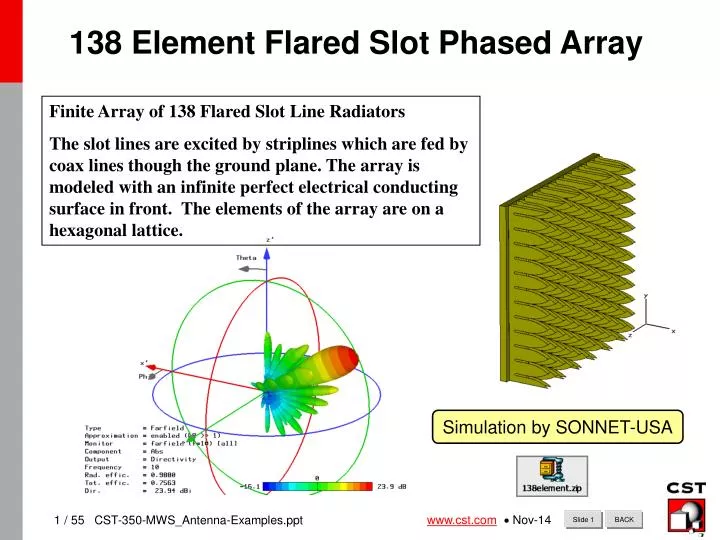
138 Element Flared Slot Phased Array. Finite Array of 138 Flared Slot Line Radiators

E N D
138 Element Flared Slot Phased Array Finite Array of 138 Flared Slot Line Radiators The slot lines are excited by striplines which are fed by coax lines though the ground plane. The array is modeled with an infinite perfect electrical conducting surface in front. The elements of the array are on a hexagonal lattice. Simulation by SONNET-USA Database-Slide
138 Element Flared Slot Phased Array E(1, 1): TEM-mode, Line Imp. 52 Ohms Each of the 138 coax lines are excited with their normal mode (TEM). The coax lines are near 50 ohms. Database-Slide
138 Element Flared Slot Phased Array excitation returns Port Signals The coax lines are simultaneously excited with a broadband Gaussian pulse. This is done so that broad band s-parameters can be obtained. The return signals at the various ports is also monitored. This simulation required 400 Mbytes of RAM and 1.5 hrs on a 600 MHz PIII laptop. Database-Slide
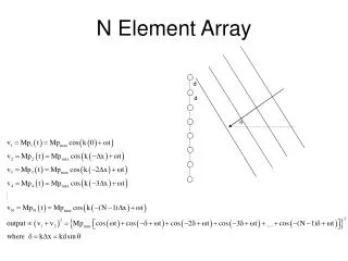
138 Element Flared Slot Phased Array Port Phasing If all the ports were excited at the same time, the resultant beam would be normal to the plane of the array. To point the beam off axis, the excitation can be phased, if using a monotonic cw excitation, or delayed in time for a broad band excitation. We used a time delay which would point the beam 30 degrees off axis in the y-direction. To do this, each row of the array was given a different delay; (r/c)*sin(), where r is the y location of the row, c is the speed of light, and is the desired beam angle off the x-axis. This figure shows the excitation of rows at the bottom, middle, and top of the array. Database-Slide
138 Element Flared Slot Phased Array Parameterization and Port Excitation In building a model in Microwave Studio, you may use parameterization. A list of parameters is set up and these can be used to define the geometry, materials, excitation, etc. For this model a parameter (p) was defined to be the phase shift in the excitation between the rows; left figure. The total phase shift for a row (p10 for example) was then defined as a multiple of this basic quantity. Then when the model was excited, the ports were excited with unity amplitude and a phase shift set for its row; right figure. Database-Slide
138 Element Flared Slot Phased Array Driven Returns All of the ports are excited so you cannot get a standard Snn for the array but rather a set of “driven” returns; returns when more than one port is excited. Port 1 (red) is at the top corner of the array. Its return differs from that of Port 3 (dark blue, top middle of the array). But the difference with elements further down in the array is even greater because the coupling of the signals is stronger there. Note that the driven return at an element can go positive if it is coupling energy out of neighboring elements. Database-Slide
138 Element Flared Slot Phased Array Electric Field at 10 GHz The electric field was saved at 10 GHz. This figure shows the field on a plane parallel to the array face. Because of the phasing, the hexagonal element pattern, and the finite size of the array, there is no symmetry to the field. Database-Slide
138 Element Flared Slot Phased Array Far-Field Radiation Pattern The radiation pattern for the array was captured at 10 GHz. This figure shows the pattern with the same orientation as the geometry shown earlier. You can see that he beam has been pointed off-axis. You can also see numerous side lobes to the pattern Database-Slide
138 Element Flared Slot Phased Array Far-Field Radiation Pattern The far field pattern can also be plotted on a 2D ( , ) scale. You can see that the main beam has been moved off normal ( = 90) and again you can see the side lobes. You can also see that the pattern is not symmetric (right/left). Database-Slide
138 Element Flared Slot Phased Array Polar or Cartesian plots of cuts through the radiation pattern can be made. In this polar plot you can see that the main beam is at 61 degrees, not 60 degrees as calculated from the array function. This deviation comes from several sources: the finite size of the array, the element pattern, and element to element coupling. You can see that the side lobe level is –11.2 dB relative to the main beam. If we wanted to suppress this, we could amplitude weight the excitations. A Taylor, cosine or other weighting is often used to drop the strength of the excitations at the edges of the array and suppress the side lobes. Far-Field Radiation Pattern Database-Slide