Download
1 / 17
170 likes | 178 Views
Dual Pumping . Definition: An operation where a strong hydrant is used to supply two Engines by connecting the Engines intake-to-intake. The second Engine receives excess water not being pumped by the first Engine, which is directly connected to the water supply source. Eng 1. Dual Pumping .

E N D
Dual Pumping • Definition: An operation where a strong hydrant is used to supply two Engines by connecting the Engines intake-to-intake. The second Engine receives excess water not being pumped by the first Engine, which is directly connected to the water supply source.
Eng 1 Dual Pumping • Operations: • Step 1: Engine 1 connects to the hydrant steamer connection using LDH. This Engine then pumps water through its line(s) to the fire.
Eng 1 Eng 2 Dual Pumping • Operations: • Step 2: Engine 2 is positioned intake to intake with Engine 1. The hydrant is closed down until the compound gauge of Engine 1 reads near zero. (Engine 1 throttle may need adjusting). This makes the volumes of discharge and intake equal, so the cap of the unused intake can be removed. {If Engine 1 is equipped with a gate valve on its unused intake, the hydrant need not be turned off.}
Eng 1 Eng 2 Dual Pumping • Operations: • Step 3: Engine 2 is connected by Hard suction to the unused steamer intake of Engine 1. • Step 4: Hydrant is opened completely.
Dual Pumping • Operations: • Step 5: Engine 2 pumps water through its line(s) to the fire. Its supply is the water not being used by Engine 1 that is passing through Engine 1’s pump. Eng 2 is getting the left over hydrant intake pressure Eng 1 Eng 2
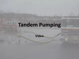
Tandem Pumping • Definition: A short relay operation in which the pumper taking water from the supply source pumps into the intake of the second Engine. The second Engine boosts the pressure of the water even higher. This method is used when pressures higher than the capability of a single Engine are required.
Tandem Pumping • The higher pressures result from the fact that the pumps are actually acting in series.
Tandem Pumping • Tandem Pumping Operations: • 1. Attack engine short distance from a hydrant. • 2. 2nd Engine placed directly on hydrant to support supply lines to attack engine. • 3. May also be used to overcome friction loss problems that occur in large sprinkler or standpipe systems and in long hose layouts. • 4. Caution should be used as to not over pressure at which the hose is annually tested.
300 PSI needed 70 psi 80 psi 150 psi 300 psi 220 psi = + = + Tandem Pumping You are making a 2 stage pump, using 2 engines with single stage pumps
Relay Pumping • Definition: The process of using 2 or more Engines to move the water through hoselines over a long distance by operating the Engines in series.
Relay Pumping • As soon as the source engine gets water, advance the throttle to the calculated pressure. • At the same time allow water to waste through an open discharge (dump line). Dump discharge
Source Engine 1st Relay Engine Dump discharge Stop Dump discharge Relay Pumping • When the first relay engine is ready for water, the operator for the source engine opens the valve for the supply line, closes the open discharge (dump line) stopping the waste flow, and starts water moving toward the fire scene.
2nd Relay Engine Dump discharge 1st Relay Engine Stop Dump discharge Relay Pumping • When water reaches the first relay engine, it is allowed to flow through the uncapped discharge (dump line) as waste water until air is forced out. • The engine is then engaged and the throttle advanced to establish the specified pressure while adjusting the valve on the uncapped discharge (dump line) to maintain 50 p.s.i. on the intake. Source Engine
2nd Relay Engine Relay Pumping Stop Dump discharge Fire Scene Engine • Each engine in turn duplicates the previous steps until water arrives at the fire. • The engine at the fire establishes the pump discharge pressure needed to provide the required nozzle pressure on all lines. • All engines will set relief valves or pressure governors. 1st Relay Engine Source Engine
Relay Pumping • Any adjustment of pressure at relay engines can only be made when gauges readings clearly indicate changes are necessary. • The engine at the fire is shut down first by slowly decreasing pressure until the pump can be disengaged.
Relay Pumping • Water is allowed to waste through the uncapped discharge (dump line) once again. • Each engine in turn reduces pressure gradually and allows the water to waste after the pump is disengaged. • Good communications is a must for a successful relay operation
Relay Pumping • Source: • IFSTA Fire Department Pumping Apparatus