Download
1 / 8
100 likes | 194 Views
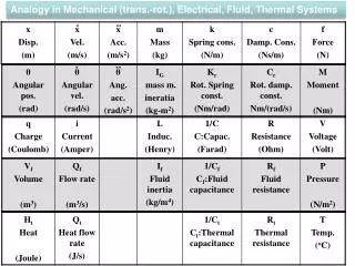
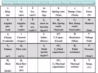
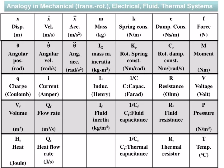
Analogy in Mechanical (trans.-rot.), Electrical , Fluid , Thermal Systems. Reynolds Number=. D.Rowell & D.N.Wormley, System Dynamics:An Introduction, Prentice Hall, 1997. Fluid inertia in pipes:. I f :Fluid inertia, ρ : Density, L: Pipe length A: Cross section of pipe.

E N D
Analogy in Mechanical (trans.-rot.), Electrical, Fluid, Thermal Systems . .. . ..
Reynolds Number= D.Rowell & D.N.Wormley, System Dynamics:An Introduction, Prentice Hall, 1997 Fluid inertia in pipes: If:Fluid inertia, ρ: Density, L: Pipe length A: Cross section of pipe Fluid reservoir capacitance: Cf: Fluid reservoir capacitance , Ad:Cross section area of reservoir, g=9.81 m/s2 Fluid resistance of pipes in laminar flow: Rf:Resistance, µ:Viscosity, L:Pipe length, d:Pipe diameter Reynolds number in laminar flow<2000
pa Qk1 2 Qn 5 1 4 2 3 1 pk1 Q5 Q3 Equivalent Electrical Circuit of Fluidic Systems In this lesson, we will learn and study the modeling fluidic systems by creating equivalent circuits.There is an analogy between the fluidic and electrical quantities. Let’s consider Example 5.1. A fluidic system is given here. We will create the equivalent circuit for the system by using the analogy. Example 5.1 Fluid.Elec. pn Vn Rn Rn In Ln Cn Cn
Fluid.Elec. Qn 1 pk1 L1 R1 Vk1 + - Va pa pn Vn Fluidic System Rn Rn In Ln Cn Cn In the fluidic system the pumps is connected the pipe #1. The pump’s output pressure is Pk. The atmospheric pressure is Pa. The top of the tank #1 is open to the atmosphere. In the electrical circuit, a supply voltage operating at Vk-Va is connected to the resistor R1 and inductor L1. R1 represents the resistance to a flow in the pipe #1. L1 represents the inertia of a flow in the pipe #1. Equivalent Electrical Circuit
In the fluidic system the tank #1 is connected to both of the pipe #1 and the pipe#2. However, in the electrical system, the capacitor #1 is connected to both of the resistor R1, inductor L1 and the resistor R2, inductor L2. The other end of the capacitor #1 is connected to the voltage Va because the tank #1 is open to the atmospehere. The capacity of a tank in a fluidic system corresponds to a capacitor in an electrical circuit. There is an external flow with the flow rate Qk1 in the fluidic system. The current supply qk1_dot is placed in the electrical circuit. Qk1 1 1 pk1 2 L2 R2 C1 L1 R1 Vk1 + - Va pa Fluidic System Equivalent Electrical Circuit
In the fluidic system, the pipe #2 is connected to both of the pipe #3 and the pipe#4 at the point A. On the other hand, in the electrical system, the line with the resistor R2, inductor L2 is connected to the lines the resistor R3, inductor L3 and the resistor R4, inductor L4 at the point A. Qk1 1 1 pk1 4 2 3 A L4 L3 L2 R2 R3 R4 V4 - + C1 L1 R1 Vk1 + A Q3 - Va pa Fluidic System There is a pressure P4 in the pipe #4 due to the placement of pipe #4 in the vertical direction because the flow is opposite to the gravity in pipe #4. So, the voltage supply V4 is placed in the circuit due to the analogy. The positive end of the V4 is connected to the point A. The current produced from V4 flows in the opposite direction. Equivalent Electrical Circuit
Qk1 2 5 1 1 pk1 4 2 3 A C2 L3 L4 L5 L2 R2 R5 R3 R4 V4 - + C1 L1 R1 Vk1 + A Q3 Q5 - Va pa Fluidic System In the fluidic system the tank #2 is connected to both of the pipe #1 and the pipe#2. On the other hand, in the electrical system, the capacitor #2 is connected both of the resistor R4, inductor L4 and the resistor R5, inductor L5. Equivalent Electrical Circuit
Electrical systems can be analyzed instead of fluidic systems Dynamic (Transient) behaviour Steady-state behaviour By analyzing the equivalent circuit, transient or steady-state dynamic behavior at a desired point of a circuit can be calculated. Thus, the corresponding flow rates and pressures at a desired line of a fluidic system are found. Nowadays computer aided engineering (CAD/CAE) is used. Nowadays, circuits and fluidic systems can be modeled and analyzed by the computers. Before the developments in computer technology, in order to analyze fluidic systems engineers have used the equivalent circuits, which are produced easily and cheaply. Complex fluidic systems have been easily analyzed with the experiments of circuits.