Download
1 / 14
140 likes | 150 Views
This article discusses the feasibility and performance of a low-cost LRPT receiver for direct broadcast transmission of satellite weather images. The study includes simulations in different RF environments and evaluates the receiver's performance in terms of bit error rate and coverage.

E N D
Prototype LRPT Receiver NOAA Satellite Direct Readout Conference for the Americas December 9-13, 2002 Miami, FL Wai Fong NASA/GSFC Code 567 Microwave and Communications System Branch wai.h.fong@.nasa.gov
Background • Low-Resolution Picture Transmission (LRPT) is a proposed standard for direct broadcast transmission of satellite weather images for METOP • LRPT definition is a joint effort by EUMETSAT and NOAA • Goddard Space Flight Center was tasked to build an LRPT Demonstration System (LDS) and study the protocol performance
Objective • To develop and demonstrate the feasibility of a low-cost receiver utilizing as much Commercial-off-the-shelf (COTS) equipment as possible. • Determine the performance of the protocol in a simulated Radio Frequency (RF) environment.
Approach • Utilize Personal Computers as the primary processing component. • Develop all software elements to process and control data flow. • Identify and procure COTS RF modulator/demodulator (MODEM). • Utilize the Institute for Telecommunications Sciences (ITS) study for modeling two noise environments: Residential (Lakewood, CO) and Business (Downtown Denver, CO). • Perform BER analysis of protocol and simulate a satellite pass. • Use Modulated Lapped Transform (MLT) instead of current JPEG variant.
Transmitter Description • Compress, channel code and CCSDS format AVHRR data off-line and store in the Transmitter buffer • RF Modem performs QPSK modulation
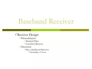
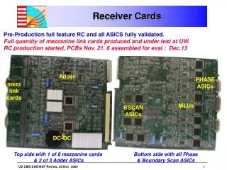
Key Features of the Receiver • Hardware elements: • Modem performs QPSK demodulation • Bit synchronization producing 3-bit soft-decision samples • Real-time Software elements: • Unique Word (UW) synchronization • Convolutional de-interleaving • Viterbi decoding • CCSDS Frame Synchronization • CCSDS Block de-interleaving • Reed-Solomon decoding • CCSDS Virtual-Channel processing • CCSDS Packet processing • Modulated Lapped Transform (MLT) decompression • Image Display • Status/Statistical analysis and display
Noise and Scintillation Generation • Noise and Scintillation patterns are generated by ITS models. • Use Pattern Generators to drive programmable attenuators and phase shifters.
Summary of Results • 40% of the CPU bandwidth required for Receiver processing. • 7 dB of coding gain at the output of the Viterbi decoder @ 10-4 BER in a residential environment with Man-made/Gaussian noise and Scintillation. • Coding gain decrease to 5.2 dB as the Man-made noise increased for the urban environment. • Use of convolutional interleaving can provide as much as 2 dB of gain. • The output of the R-S decoder was virtually error-free as long as the receiver maintained solid lock. • For residential (low noise) environments e.g. Lakewood, nearly 100% coverage for either Yagi or Omni antenna. • In high noise urban environments like Downtown Denver, 65% coverage using an Omni antenna.
Conclusion • Protocol mitigates scintillation and man-noise effects. • In larger more populated metropolitan areas, use a tracking Yagi antenna and/or a better receiver due to the noisier environment. • Inexpensive LRPT receivers can be made by using software to perform most of the receiving functions.
Demonstration • Pass simulation of Downtown Denver with Omni Antenna in Man-made noise/Gaussian noise and Scintillation • Pass simulation of Lakewood with Yagi Antenna in Man-made noise/Gaussian noise and Scintillation