Download

1 / 34
660 likes | 2.62k Views
Band Loop Space Maintainer. Jabbarifar: Pedo- Technique Lab 2009. Progression of Skills. Space Maintainer. Flame Soldering. Wire Bending. Background Information.

E N D
Band Loop Space Maintainer Jabbarifar: Pedo- Technique Lab 2009
Progression of Skills Space Maintainer Flame Soldering Wire Bending
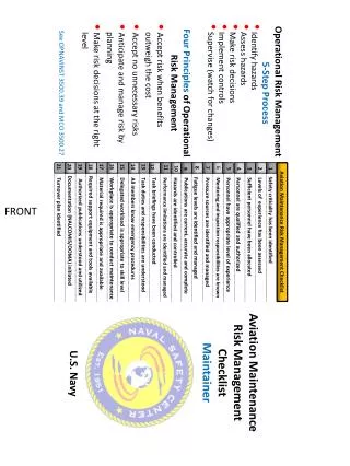
Background Information • The most common situation requiring the use of a band loop space maintainer is the premature loss of a first or second primary molar.
What You Need Today! • your patient (maxillary model) • #14 metal impression tray • green stick compound • alginate (provided) • band adapter/band seater/band removing pliers (optional) • bird beak, 3 prong, wire cutters • soldering materials • molar band (RU 34)
Band Selection • Select smallest band that will fit over the height of contour of the tooth • First seat band with digital pressure
Band Adaptation • Utilizing band seater with the lead peg on the occlusal margin of the band fully seat the band
Band Adaptation • Utilizing the band adapter adapt margins to the tooth morphology
Properly Adapted Molar Band • Occlusal margin ofband is apical to the proximal ridges • Gingival margin of the band is in the gingival sulcus • Band is snugly adapted to the tooth’s surface • Band is out of occlusion
Band Removal • Utilize the band removing pliers • Pliers have a plastic covered knob which is placed on the occlusal surface of the tooth and the sharp lower edge is placed under the gingival margin of the band • Pliers are squeezed which raises the band onto the upper beak of the pliers
Compound Index • Make compound index • lubricate tooth • do not overheat compound • Compound index should completely cover occlusal surface of band, extending 2mm past the band • if index is too large it will be dislodged when impression tray with alginate is placed
Alginate Impression • Take alginate impression • Compound index should come off tooth and be embedded in the alginate impression • Check that the occlusal margin of the band is clearly reproduced • Remove band and orient in compound index • Stabilize band with sticky wax • on buccal and lingual at the occlusal aspect of band Sticky Wax
Pour Impression • Use white plaster • if you are going to abrade cast might want to use stone • Prepare flat base so that cast does not rock during fabrication of appliance
Draw Design of Band Loop Space Maintainer on Cast • The mesial end of the loop contacts the distal surface of the first primary molar at a point just below the height of contour • The wire should be above the gingiva at the point of contact with the abutment tooth
Design of Band Loop Space Maintainer • The central portion of the loop is shaped wideenough to allow the full eruption of the permanent tooth • the bucco-lingual width of a maxillary premolar is 9mm • The loop should be contoured to follow the edentulous ridge, but 1mm off the tissue • The anterior curve of the loop is shaped to approximate the shape of the distal surface of the abutment tooth and to match its width
Bending the Wire • Cut about a 3 inch segment of .036 wire • At the midpoint of the wire make a “w” shaped curve
Check Anterior Curve • Check the curve against the abutment tooth on the cast to see that it is approximately the width of the first primary molar and does not extend beyond the disto-buccal line angle
Lowering the Sides • Position the pliers with the single beak on the gingival surface of the wire under the center of the “w” shaped curve • Squeeze pliers gently
Mesial End of Distal Legs • Form a gradual curve to parallel the gingival crest of the alveolar ridge by ‘walking’ the 3 prong pliers distally over the wire • Complete one leg before proceeding to other leg
Mesial End of Distal Legs • Continue bending in small increments until the desired arc is achieved • The wire should be approximately 1mm off the tissue
Step Bend • Mark wire far enough mesially to allow the finished s-bend to be completed before reaching the band.
Step Bend • Place the conical beak of the bird beak pliers on the occlusal portion of the wire and bend the distal portion of the wire upward against the conical beak
Step Bend • Place the conical beak of the bird beak pliers on the gingival portion of the wire and bend the distal portion of the wire downward against the conical beak
Step Bend • Purpose of S-bend • allows transition of wire from the ridge to band without impinging on the gingival tissues
Distal Ends • Bend distal ends of loop to rest passively against the junction of the middle and occlusal third of the clinically exposed band
Distal Ends • Use simple bends to contour the wire so it contacts the band near the mesial line angle and remains in contact for the full length of the band • Cut away any excess wire or plaster that interferes with fitting
Prepare to Solder • Stabilize the wire in position on the cast with wax • Wet anterior end of cast to prepare it for the application of plaster which will be used to secure the loop • Apply creamy mix of quick setting plaster Plaster Wax
Prepare to Solder • When plaster has reached its initial set, remove sticky wax • Remove the plaster from the inside of the bands adjacent to the soldering sites • Remove all particles of wax, plaster and debris from soldering site Plaster
Criteria for Solder • The solder: • encircles the wire • extends the full length of the contact area between the wire and the band • The occlusal and gingival margins of the band are free of solder • The surface of the solder joints are free of pitting and voids • The wire mesial to the solder joints has not been annealed
Polishing • Use a heatless stone to reduce the distal ends of wire to form to a smooth curve continuous with the band • The ideal solder joint is concave • If a minimum of solder has been used, the joints will be concave and solder will not extend to the margins of the band • Appliance is finely polished, cleaned and dried W Band Distal Cross-section
Summary • With correct diagnosis and implementation of wire bending and soldering techniques, the potential problems associated with premature loss of a primary molar can be successfully averted.