Download

1 / 40
400 likes | 629 Views
The CMS Muon Detector Upgrade . Jeffrey Roe June 29, 2010. Overview. The Standard Model of particle physics The LHC and CMS Detector Why Muons ? Muon Detection at CMS Endcap Trigger Electronics LHC/CMS Upgrade Motivation Trigger MotherBoard upgrade.

E N D
The CMS Muon Detector Upgrade Jeffrey Roe June 29, 2010
Overview • The Standard Model of particle physics • The LHC and CMS Detector • Why Muons? • Muon Detection at CMS • Endcap Trigger Electronics • LHC/CMS Upgrade • Motivation • Trigger MotherBoard upgrade
Standard Model of Particle PhysicsHiggs Boson • The Standard Model describes fundamental particles and their interactions but has shortcomings • E.g., cannot explain the origin of particle masses • The “Higgs boson” provides a theoretical solution • A new particle, which interacts with other particles, giving them mass in the process • Search for the Higgs boson at the Large Hadron Collider (LHC): • Produce Higgs bosons in high energy collision experiments • Search for its decay products in detectors, to prove that we have seen it
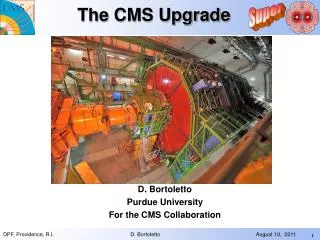
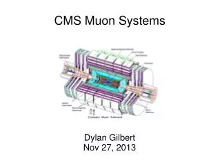
CMS Layout • The Compact Muon Solenoid (CMS) is one of two flagship detector experiments at the LHC
Why Muons?Higgs Boson and More • Search for Higgs Boson • One promising decay mode: pp H Z0Z0 μ+μ-μ+μ- • Physics beyond the Standard Model • Super Symmetry (SUSY) • New heavy “cousins” of W and Z bosons • Muons provide a “clean” signal to detect interesting events in messy backgrounds
Muon Detection at CMS • Muons are good at penetrating material • No other charged particles do this • Muon system is the farthest sub-detector from the beam • Muon system: • Barrel Region • Drift tubes (DTs) • Endcap Region: • Cathode Strip Chambers (CSCs)
End Cap Region • 468 trapezoidal shaped Cathode Strip Chambers (CSC) in 4 stations (ME1-ME4) • 6 gas gaps per chamber • Plane of radial cathode strips • Plane of nearly perpendicular anode wires • Charged particle traverses chamber which ionizes the gas in the gaps causing an electron avalanche • Produces a charge on an anode wire • Produces an image charge on cathode strip
Basics of Track ReconstructionEndcap region ME1 ME3 ME1 ME3 • You have to be able to do this in real time • Collisions happen every 25 nanoseconds! • Concept of trigger: • Can’t possibly record every event • Example: 1MB per 25ns means we would require a bandwidth of 40 million MB/sec • Must be selective about which events to keep and must be able to quickly pick which these are ME2 ME4 ME2 ME4 µ
CSC Level 1 Trigger PathElectronics, 1st level of trigger • Anode/Cathode Front End Board (AFEB/CFEB) • Anode/Cathode Local Charge Tracks (ALCT/CLCT) • Trigger MotherBoard (TMB) • Muon Port Card (MPC) • CSC Track Finder (CSCTF) ALCT (x468) AFEB (x?) CLCT (x468) CFEB (x2268) TMB (x468) MPC (x60) CSCTF (x12)
CSC Trigger PathTrigger MotherBoard (TMB) • Receives anode and cathode digitized “local charged tracks” (LCTs) separately from anode and cathode front-end electronics • Performs a timing coincidence of the all anode and cathode LCTs in 1 chamber and forms 3D tracks (stubs) • Selects up to 2 best stubs based on the number of layers hit, type of pattern, pt, etc. • Assigns vectors to the LCTs (position, direction, bunch crossing, quality) ALCT AFEB CLCT CFEB TMB MPC CSCTF FPGA
LHC Upgrade • Nominal luminosity may be too low to observe new physics phenomena or measure Higgs boson properties in a reasonable time period • Beam luminosity will be increased in the next several years • This will greatly increase number of particles per collision seen the in the detector • Detector upgrades are needed to ensure efficiency at the increased rate Collision reconstruction at current LHC intensity Collision reconstruction at upgraded LHC intensity
Monte Carlo SimulationMuon trigger efficiency • We use Monte Carlo software simulation to model • Generation of collision events • Particles passing through matter & detector electronics response • Trigger logic is emulated • Various distributions were obtained for different scenarios • Low and high luminosity • Current and upgraded muon trigger • Several trigger pt thresholds • Trigger Efficiency • Probability that the trigger will do its job for a given Monte Carlo event • d
Parameterization of muon trigger efficiency • For each scenario, efficiency depends on η and pt • We parameterize and fit each dependence with these functions: • Final efficiency function: • I wrote code that calculates this efficiency in certain scenarios which can be used in other physics studies for the upgrade
Current System at High LuminosityUnacceptable inefficiency • Without an upgrade, the current trigger must enforce a higher ptthreshold (2050 GeV/c) in order to handle the higher particle rates • This severely reduces the efficiency of the detector • Most notably in the region where the Higgs boson and other new physics are expected to be Low Luminosity High Luminosity
Upgraded Muon Trigger Acceptable rate and high efficiency • The upgraded detector will be able to handle the higher rates while still enforcing the lower pt threshold • This will dramatically increase the effectiveness of the detector in the “Higgs region” • One of the critical updates is the Trigger MotherBoard upgrade • Need to decrease the dead time • Solution requires a faster, more robust FPGA and therefore a new board design Upgraded Detector Current Detector
Trigger MotherBoard UpgradeVoltage regulator tests • Currently: • Vertex 2 FPGA • Upgrade: • Vertex 6 FPGA • Faster (x2) • More logic capability (x5) • Voltage Regulator Tests • FPGA requires several different input voltages (1V (x2), 1.2V, 1.8V, 2.6V, 2.9V) • Need to design, manufacture, and test several different regulator options for each supply • Requirements: • Operating voltage stability • Temperature • Radiation tolerance • Operation in magnetic field
Trigger MotherBoard UpgradeTest board design steps • Design circuit for each regulator to achieve required behavior • Use device datasheets • Ensure all minimums and maximums are met (current, voltage drop, power, temperature estimate) • Altium Designer • Schematic layout • Printed Circuit Board (PCB) layout
Trigger MotherBoard UpgradeTest board design steps • Manufacture Board • TAMU physics electronics shop • Drill holes • Plate with copper • Etch tracks and lines • Solder parts • Test circuits • Voltage stability • Thermal operation • Radiation tolerance
Voltage Regulator TestsVoltage testing and analysis • System requires that that voltage levels into the FPGA remain stable • Test board was powered on in the morning and the voltages of each circuit measured 3-4 times per day • Looked for irregularities in the measured voltages throughout the tests (± 10mV) • Results: All tested regulators proved stable for several days of continuous operation in the laboratory
Voltage Regulator TestsThermal testing • FlirExtech i5 Thermal Imager • Procedure • Thermal images taken periodically through the day • Several conditions were tested to simulate possible working conditions at the LHC • Natural convection • Heat sinks • Air flow
Voltage RegulatorsThermal Analysis • Measurements taken on the case of the device • Manufacturer specified maximum temperatures are given for inside chip • Converted measured “case” temperature to “junction” temperature • Junction to case thermal resistance for device is given in data sheet • Can calculate power the device dissipates • TJ = TC + PD*RΘJC • Compared ratio of each device’s measured temperature to its specified maximum Measured surface Temperature Needed junction temperature
Voltage RegulatorsThermal Analysis Results • All regulators survived the first round of thermal testing • All operated below their maximum specified junction temperature • Some were too close to their maximum to be considered safe for operation at the LHC • Heat dissipation methods: • Air flow had a big impact on the regulator temperature (~30% - 40% decrease) • Thermal heat sinks had a much smaller effect (~10% decrease) 100% of Maximum 100% of Maximum
Voltage RegulatorsStill to come… • Radiation testing in nuclear reactor • Submit to neutron radiation for specified time period to and translate this to equivalent exposure time at the LHC • Retest circuits for voltage output and operating temperature to find which devices have been degraded by the radiation • Choose the most appropriate regulator for each supply required by the FPGA by: • Radiation tolerance • Voltage and current stability • Operating temperature • Designer preference
Conclusion • We can look for the Higgs boson as well as other new physics in the LHC, but we will have to upgrade the beam • This means upgrading the electronics • A major component of the upgrade is the Trigger MotherBoard upgrade • Research and design of the upgraded TMB system is currently underway • Voltage regulators test boards have been designed and manufactured • The first round of testing (voltage, operating temperature) has been completed • Radiation testing is still to come
Barrel Region • 250 chambers organized into 4 layers • MB1-MB3: 5 wheels split into 12 sectors • MB4: 5 wheels split into 14 sectors • MB1-MB3 Chambers: • 12 planes of aluminum DTs • Top and bottom “superlayers” have 4 planes of r-φmeasuring DTs • Middle “superlayer” has 4 planes of z measuring tubes • MB4 Chambers • 8 planes of aluminum DTs • All r-φmeasuring tubes
End Cap RegionContinued • ME1 divided into 4 rings • ME1/1a, ME1/1b, ME1/2, ME1/3 • Each ring has 36 chambers covering 10° in Φ • ME2-ME4 divided into 2 rings • ME2(-4)/1, ME2(-4)/2 • Inner rings have 12 chambers covering 20° in Φ • Outer rings have 36 chambers covering 10° in Φ
CSC Avalanche Model Cathode (Gnd) Wires (+4100V) Cathode (Gnd)
CSC Trigger Path • Anode/Cathode Front End Board (AFEB/CFEB) • Report which anode wire or cathode strip groups receive hits • Anode/Cathode Local Charge Tracks (ALCT/CLCT) • Find tracks in hit patterns in cathode strips and anode wires that point back toward the collision vertex • Up to 2 cathode LCTs and 2 anode LCTs from each chamber sent to TMB • Trigger MotherBoard (TMB) • Cathode and anode projections from one chamber are combined into 3D LCTs • LCTs assigned vectors (position, direction, bunch crossing, quality) ALCT AFEB CLCT CFEB TMB MPC CSCTF
CSC Trigger Path • Muon Port Card (MPC) • Receives all LCTs from one 60° sector of 1 station of ME2-ME4 or one 20° sector of ME1 • Selects the 3 best and sends them to the CSC Track Finder (CSCTF) • CSC Track Finder (CSCTF) • Builds tracks from LCTs from different stations compatible with a muon originating from the collision vertex • Assigns transverse momentum value to the new muon track • Selects the 4 best tracks in entire CSC system and forwards them to the Global Muon Trigger (GMT) ALCT AFEB CLCT CFEB TMB MPC CSCTF
Anode Front End Boards (AFEB) CSC Trigger Path ALCT AFEB • Receives the signals from the anode wire groups • Amplifies them • Selects the signals that are over the preset threshold CLCT CFEB TMB MPC Anode Local Charged Tracks (ALCT) CSCTF • Generates 2D Anode “Local charged track” (LCT) for possible muon crossings • Stretches the hits from the AFEB to allow for the up to 50 ns drift time in the anode wires • Identifies the bunch crossing
AFEB Cathode Front End Boards (CFEB) CSC Trigger Path CLCT CFEB • Receives the signals from the cathode strips • Amplifies signals • Shapes them into semi-Gaussian voltage pulses • Locates the center of the charge clusters to a ½ strip accuracy ALCT TMB MPC CathodeLocal Charged Tracks (CLCT) CSCTF • Located on the Trigger MotherBoard • Time-stretches the incoming hits • Generates 2D Cathode LCTs by timing coincidence of hit patterns
AFEB Muon Port Card (MPC) CSC Trigger Path • Takes 2 LCTs from different stations and tests whether they are compatible with a muon originating from the collision (with appropriate field conditions) • If a match is found, the CSCTF assigns a momentum value to the muon track • Selects the 4 best muon candidates from the entire CSC system and sends them to the Global Muon Trigger ALCT CLCT CFEB • Receives all LCTs from predefined groups of chambers from the same station • Selects the 3 best and sends them via optical fiber to the CSC Track Finder (CSCTF) TMB MPC CSC Track Finder (CSCTF) CSCTF
CSC Trigger PathAnode Front End Boards (AFEB) AFEB • Receives the signals from the anode wire groups • 16 channel amplifier-shaper-discriminator ASIC • Amplifies them • Selects the signals that are over the preset threshold with precise time accuracy ALCT CLCT CFEB TMB MPC CSCTF
CSC Trigger PathAnode Local Charged Tracks (ALCT) ALCT • Stretches the hits from the AFEB to 6 bunch crossings to allow for the up to 50 ns drift time in the anode wires • Generates 2D LCT for possible muon crossings • Low coincidence level used to establish timing • Higher coincidence level used to establish the possibility of an existing muon track • Multilayer coincidence technique used to identify the bunch crossing AFEB CLCT CFEB TMB MPC CSCTF
CSC Trigger PathCathode Front End Boards (CFEB) CFEB ALCT AFEB CLCT • Receives the signals from the cathode strips • 16 channel amplifier-shaperASIC • Amplifies signals • Shapes them into semi-Gaussian voltage pulses • Comparator ASIC • Locate the center of the charge clusters to a ½ strip accuracy • Marks the time of the pulse TMB MPC CSCTF
CSC Trigger PathCathode Local Charged Tracks (CLCT) CLCT • Located on the Trigger MotherBoard • Time-stretches the incoming hits by several bunch crossings to allow for the up to 75 ns drift time in the cathode strips • Generates 2D LCTs by timing coincidence of hit patterns in the 6 layers of a chamber consistent with high momentum muon tracks ALCT AFEB CFEB TMB MPC CSCTF
Electronics Challenges • Cannot collect and reconstruct all of the events which occur during the collision • Must decide which events are “interesting” and should be kept and which events can be disregarded • Many choices to make in a short period of time in order to maintain the efficiency and integrity of the system • Products of interesting events can be confused with those of non-interesting events • High radiation environment requires radiation tolerant electronics • Large number of electronics compounds potential problems