Download
1 / 12
120 likes | 141 Views
Chapter 3: DIFFERENTIAL ENCODING. Differential Encoding Eye Patterns Regenerative Receiver Bit Synchronizer Binary to Mary Conversion. Huseyin Bilgekul E eng 360 Communication Systems I Department of Electrical and Electronic Engineering Eastern Mediterranean University.

E N D
Chapter 3: DIFFERENTIAL ENCODING • Differential Encoding • Eye Patterns • Regenerative Receiver • Bit Synchronizer • Binary to Mary Conversion Huseyin Bilgekul Eeng360 Communication Systems I Department of Electrical and Electronic Engineering Eastern Mediterranean University
Differential Coding System • Differential encoding removes the problem of Unintentional Signal Inversion. • Polarity of the differentially encoded signal may be inverted without affecting the decoded signal. Modulo-2 addition Exclusive OR
Example of Differential Coding Encoding Input sequence dn 1 1 0 1 0 01 Encoded sequence en 1 0 1 1 0 0 0 1 Reference digit Decoding (with correct channel polarity) Receiver sequence 1 0 1 1 0 0 0 1 (Correct polarity) Decoded sequence 1 1 0 1 0 0 1 Decoding (with inverted channel polarity) Received sequence 0 1 0 0 1 1 1 0 (Inverted polarity) Decoded sequence 1 1 0 1 0 0 1 • Decoded sequence is same whether there is inversion or not.
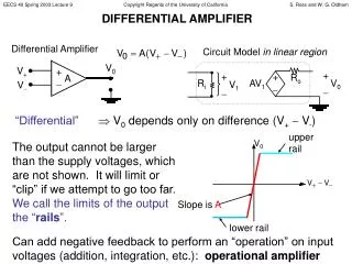
Eye patterns • The effects of channel filtering and channel noise can be seen by observing the received line code on an oscilloscope. Received Line Code Information from Eye Pattern • Timing error Eye opening • Sensitivity Slope of the open eye • Noise Margin height of the eye opening
Regenerative Repeater • Regenerate a noise-free digital signal. Amplify and clean-up the signal periodically Produces a high level o/p if sample value>VT Increases the amplitude Produces a sample value Minimize the effect of channel noise & ISI Generates a clocking signal
Synchronization • Synchronization signals are clock-type signals necessary within a receiver for detection of data from the corrupted input signal. • Digital communications need at least 3 types of synchronization signals. • Bit Synchronization (Bit Synch.): To distinguish bit intervals. • Frame Synchronization(Frame Synch.): To distinguish groups of bits. • Carrier Synchronization: For bandpass signals with coherent detection. • Syncsignals are derived from • Corrupted input signal. • From a separate channel that transmits sync signals.
Bit Synchronizer for NRZ Signals • Derive the synch signal from the corrupted received signal. • Used for unipolar NRZ signals. • Synchronizer complexity depends on the line code used. • Synchronizarion of RZ signals is easier since PSD has delta at f=R=1/Tb. • Bit synchronizer for NRZ signals is given below.
Square-law Bit Synchronizer for NRZ Signals • Square Law Device converts polar NRZ signal to unipolar RZ format. • Unipolar RZ signals have delta in the PSD at f=R=1/Tb. • This frequency component can be obtained by filtering. • Filtered sinusoidal is converted to clock pulses using a comparator.
Binary-to-multilevel polar NRZ Signal Conversion • Binary to multilevel conversion is used to reduce the bandwidth required by the binary signaling. • Multiple bits (l number of bits) are converted into words having SYMBOL durations Ts=lTb where the Symbol Rate or the BAUD Rate D=1/Ts=1/lTb. • The symbols are converted to a L level (L=2l) multilevel signal using a l-bit DAC. • Note that now the Baud rate is reduced by l times the Bit rate R (D=R/l). • Thus the bandwidth required is reduced by l times. Ts: Symbol Duration L: Number of M ary levels Tb: Bit Duration l: Bits per Symbol L=2l D=1/Ts=1/lTb=R/l Bnull=R/l
Power Spectra for Multilevel Polar NRZ Signals (c) L = 8 = 23 Level Polar NRZ Waveform Out
Spectral Efficiency Spectral efficiency for multilevel signaling is • The Spectral efficiency of a digital signal is given by, where R is the data rate and B is the bandwidth required. • If limited BW is desired, then use a signaling technique that has high spectral efficiency. • Maximum spectral efficiency (which is limited by channel noise) is given by the Shannon’s Channel Capacity formula:
I å = R ( k ) ( a a ) P + n n k i i = 1 i Ps(f) PSD of a multilevel polar NRZ waveform PSD for a multilevel polar NRZ signal: • Multilevel signaling is used to reduce the BW of a digital signal