Download
1 / 12
120 likes | 267 Views
Preliminary Engineering Report nEDM Central Detector. John C. Ramsey Los Alamos National Laboratory. Objectives. Sound out assumptions Materials choices Design rationale Component placement Interfaces with other subsystems Voice concerns See list above!

E N D
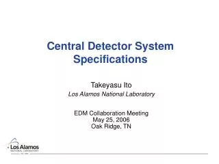
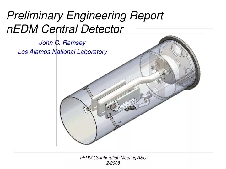
Preliminary Engineering ReportnEDM Central Detector John C. Ramsey Los Alamos National Laboratory nEDM Collaboration Meeting ASU 2/2008
Objectives • Sound out assumptions • Materials choices • Design rationale • Component placement • Interfaces with other subsystems • Voice concerns • See list above! • Obtain feedback and initiate communications nEDM Collaboration Meeting ASU 2/2008
Major assembly assumptions • What is here is in no way set in stone! • Assembly cantilevered off of central volume composite end plate • Material of choice wherever possible is acrylic (PMMA) to minimize thermal contraction mismatches • We are able to coat the acrylic for the electrodes and return • No metal components closer than 1 meter upstream of the end plate • Light guides not currently included in the model nEDM Collaboration Meeting ASU 2/2008
Central volume cap • Mounting plate for entire cantilevered assembly • Feedthroughs for light-guides, services, etc. • Assumptions • G-10 is superfluid tight provided low enough stress levels • 1.5” thick G-10 with carbon fiber reinforcing plate • Windows are large enough to compensate for thermal contraction • We can seal G-10 cap to G-10 vessel • We can seal the feed-throughs nEDM Collaboration Meeting ASU 2/2008
Acrylic interface plate • Large contraction mismatch between acrylic and G-10 • Radial slots keep back plate concentric as acrylic contracts • Supports entire cantilevered assembly • Studs and Belleville washers may replaced with PTFE glides nEDM Collaboration Meeting ASU 2/2008
HV return and support • Provide structural support to all components • Additional support tube handles axial loads from the capacitor • HV return is coated (striped?) for conductivity nEDM Collaboration Meeting ASU 2/2008
Electrode assemblies • Hollowed acrylic • Coated for conductivity • Acrylic supports to HV return • Hidden from E-field • One or more coated to provide HV return path? nEDM Collaboration Meeting ASU 2/2008
Light guide and cell assemblies • Level of detail currently low • Assuming glued box for the cells • Can we make a well performing, separable mechanical joint for the light-guide/cell interface? • Light-guides need support at multiple locations nEDM Collaboration Meeting ASU 2/2008
3He service to the measurement cells • 2” OD, 1.5” ID acrylic piping (per George’s current assumptions) • Bellows to allow for system contraction • Bell crank actuated V1 valve nEDM Collaboration Meeting ASU 2/2008
SQUIDs • Silicon substrate resting on acrylic pads • Located with a pair of pins on the V1 valve housing (not shown) • Placement along cell centerline makes V1 valve packaging very difficult and compromises the cell opening • Splitting up the SQUID array? nEDM Collaboration Meeting ASU 2/2008
V1 Valve • Torlon return spring – to be tested • Rod or rope actuation of bell crank • Larger area housing body • 0.75” cell penetration • Very tight requirements for cell wall surface quality with valve closed • Acrylic is very brittle…vespel? d-vespel? • Flushing pipes with V1 valve closed? nEDM Collaboration Meeting ASU 2/2008
Current and future efforts • FEM models • Simple 2” disc transient thermal model • to examine stresses induced by cool down rate • Full assembly • Gravity, other structural loads • Thermal contraction • Cooldown simulation • G-10 seal test vessel • Continue iterations and development in coordination with the various relevant subsystems nEDM Collaboration Meeting ASU 2/2008