Download
1 / 12
120 likes | 199 Views
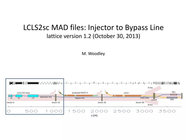
LCLS2sc MAD files: Injector to Bypass Line lattice version 1.2 (October 30, 2013). A-line. SXU. proposed FACET-II. LCLS-II SC Linac. LCLS-I. extension line. c ross-over. L1. L2. L3. bypass line. H XU. m -wall. Sector-0. Sector-10. Sector-20. Sector-30. B -line. s (m).

E N D
LCLS2sc MAD files: Injector to Bypass Line lattice version 1.2 (October 30, 2013) A-line SXU proposed FACET-II LCLS-II SC Linac LCLS-I extension line cross-over L1 L2 L3 bypass line HXU m-wall Sector-0 Sector-10 Sector-20 Sector-30 B-line s (m) M. Woodley
new linac beam axis defined • X= +0.28 m , Y= -0.99 m w.r.t. original linac axis • Z= original linac Z-coordinate • Z= 0 at start of LI01 • Z= -20 m at cathode
LCLS-II - Linac and Compressor Layout for 4 GeV L2 j = -21° V0=1447 MV Ipk = 50 A Lb = 0.56 mm L3 j = 0 V0=2409 MV Ipk = 1.0 kA Lb = 0.024 mm L0 j= * V0=94 MV Ipk = 12 A Lb = 2.0 mm L1 j =-21° V0=223 MV Ipk = 12 A Lb =2.0 mm HL j =-165° V0 =55 MV CM01 CM2,3 CM15 CM35 CM04 CM16 3.9GHz LTU E = 4.0 GeV R56 = 0 sd 0.016% 2-km LH E = 95 MeV R56 = -14.5 mm sd = 0.05 % BC1 E = 250 MeV R56 = -55 mm sd = 1.4 % BC2 E = 1600 MeV R56 = -60 mm sd = 0.46 % GUN 0.75 MeV 100-pC machine layout: Oct. 8, 2013; v21 ASTRA run; Bunch length Lb is FWHM Includes 2-km RW-wake * L0 cav. phases: ~(3.4, -15.2, 0, 0, 0, 15, 15), with cav-2 at 22% of other L0 cavity gradients.
Gun + L0 98 MeV β = 7.5435 m α = -0.2173 750 KeV • Egun = 750 KeV • Einj = 98 MeV • L0 : • 8 cavity cryomodule (layout courtesy XFEL Mad deck) • gradients and phases per P. Emma layout (version of October 8, 2013) • initial Twiss are “artificial” • final Twiss from C. Papadopoulos ("GUN2013_10_08v3“)
Matching + Laser Heater + L1 250 MeV 98 MeV • Einj = 98 MeV • EBC1 = 250 MeV • 6 quadrupole matching section between L0 and Laser Heater • Laser Heater chicane: • lengthened version of LCLS system (L= 3.529 m) • ηmax= 7.5 cm, R56= 14.5 mm • βX = βY = 10 m (α = 0) at center of chicane • includes momentum collimator • space for kicker (L= 2 m) and long drift (L= 8 m) provided for extraction to diagnostic line • L1 : • 2 x 8 cavity cryomodules(layout courtesy XFEL Mad deck) … φ= -22° • 3 x 4 cavity harmonic linearizer cryomodules (3.9 GHz) … φ= -165° • 90° FODO lattice
BC1 + Betatron Collimation • EBC1 = 250 MeV • BC1 chicane : • copy of LCLS system • R56= 55 mm • small βX at fourth bend (CSR) • space for kicker (L= 2 m) and long drift (≈ 15 m total) provided for extraction to diagnostic line • betatron collimation system : • 2 x 90 ° FODO cells (Lcell ≈ 16 m) • β = 25 m at collimators (2 x horizontal collimation + 2 x vertical collimation)
L2 1.6 GeV 250 MeV • EBC1 = 250 MeV • EBC2 = 1.6 GeV • L2 : • 12 x 8 cavity cryomodules(layout courtesy XFEL Mad deck) … φ= -21° • 30° FODO lattice
BC2 + Betatron Collimation • EBC2 = 1.6 GeV • BC2 chicane : • copy of LCLS system • R56= 60 mm • small βX at fourth bend (CSR) • space for kicker (L= 2.5 m) and long drift (≈ 30 m total) provided for extraction to diagnostic line • betatron collimation system : • 2 x 90 ° FODO cells (Lcell ≈ 24 m) • β = 38.4 m at collimators (2 x horizontal collimation + 2 x vertical collimation)
L3 + Extension to LI10 4.0 GeV 1.6 GeV • EBC2 = 1.6 GeV • Efinal = 4.0 GeV • L3 : • 20 x 8 cavity cryomodules(layout courtesy XFEL Mad deck) … φ= 0 • 15° FODO lattice • L3 extension : • 4 x 90° FODO cells (Lcell= 45 m) • at start of Bypass Dogleg, Z= 936.872 m (≈ 22.5 m into LI10)
Bypass Dogleg + Match to Bypass Line FODO • Efinal = 4.0 GeV • dogleg bending system : • from X/Y = +0.28/-0.99 m to X/Y = -0.650494/+0.649478 m (ΔX/ΔY = -0.37/+1.64 m) • two 1.06° bends, rolled to 60.4° • 4 x 90° FODO cells (Lcell= 25.4) cancel dispersion in both planes • momentum collimator and wire scanner included • total Z-length = 102.5 m
To Do for “Baseline” release • update compression parameters to latest version of P. Emma layout • use M. Venturini’s laser heater undulator parameters • exchange X and Y collimators in HXR diagnostics section • upload files to SharePoint site • MAD8 input files • MAD8 output files • ELEGANT input files • generate upload files for Oracle Database To Do after“Baseline” release • reduce chromaticity of initial matching section (L0 to LH) and other sections identified by Paul • design extraction systems and diagnostic lines (LH, BC1, BC2) • more relaxed β-functions in L2 and L3 (FFODDO rather than FODO?) • add correctors, BPMs, and other diagnostics • more …
https://portal.slac.stanford.edu/sites/lcls_public/lcls_ii/beamline_optics/wiki_lib/Home.aspxhttps://portal.slac.stanford.edu/sites/lcls_public/lcls_ii/beamline_optics/wiki_lib/Home.aspx