Download
1 / 42
920 likes | 2.4k Views
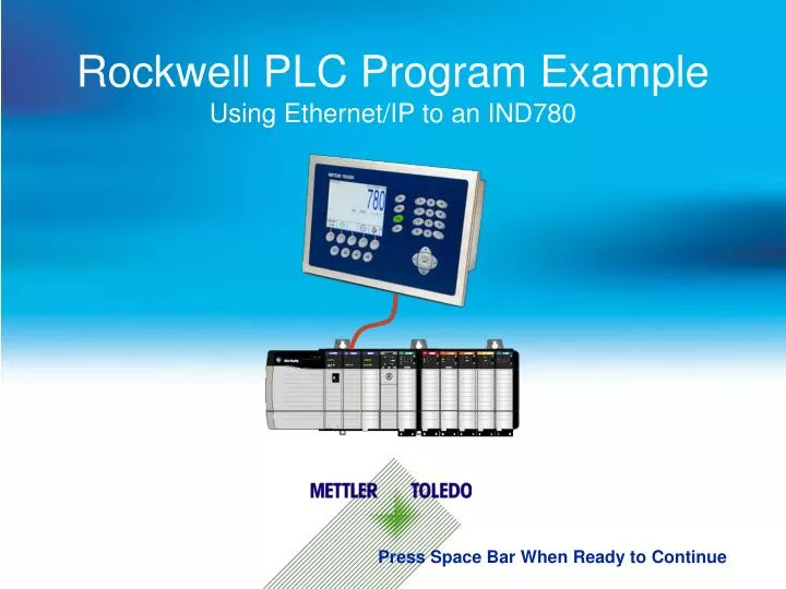
Rockwell PLC Program Example Using Ethernet/IP to an IND780. Press Space Bar When Ready to Continue. Ethernet/IP: Major Points to know before starting. There are two types of messages used : Cyclic (Implicit) messages – UDP (priority on timing).

E N D
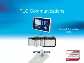
Rockwell PLC Program ExampleUsing Ethernet/IP to an IND780 Press Space Bar When Ready to Continue
Ethernet/IP: Major Points to know before starting • There are two types of messages used: • Cyclic (Implicit) messages – UDP (priority on timing). • Discrete (Explicit) –TCP/IP (priority on robustness). • Two Cyclic Data Formats Available: • Floating Point • Integer / Division • To get VALID Cyclic data it is essential to: • Use the Data OK Bit • Use BOTH Data Integrity bits OR the Update-In-Progress bit. • Select the proper Byte Order (usually Word Swap for ControlLogix) • Don't usethe Electronic Data Sheet (EDS) file Generated Add On Profile (AOP)! Press Space Bar When Ready to Continue
CIP Class 1 Communications : Cyclic Data (Implicit Messaging) Cyclic data is information that is transferred automatically between the PLC and the Terminal on a Scheduled basis. For example, the PLC may set up the Request Packet Interval (RPI)time of 25 milliseconds, which means that the messages will be exchanged (both directions) every 25 milliseconds. If a "little burp" occurs and a cyclic message gets lost, it's not usually a problem because another cyclic message will be along shortly. No complicated retry logic is necessary! Cyclic Data Cyclic Data Because Cyclic data is composed of smaller UDP packets that do not require handshaking between the devices, their timing can be faster and more deterministic – which means they are great for Automation Control purposes. Press Space Bar When Ready to Continue
CIP Class 3 Communications : Discrete (Explicit) Messaging Discrete (explicit) data is information that is transferred between the PLC and the Terminal on demand – in other words, only when it is needed. For example, the PLC may need to tell the Terminal to do a tare or start a feed. These messages need to get to their destination reliably, but only once. If a "little burp" occurs and a discrete message gets lost or corrupted, the TCP/IP protocol uses "Checksum and Acknowledged or Not Acknowledged" technology to retry the message until it succeeds or times out. These messages can be much longer than the cyclic data messages! Retry - Tare Tare CMD Ack Because Discrete messages are sent at a LOWER priority, and go through the Handshaking process, they should not be used for anything that is time critical. Press Space Bar When Ready to Continue
Ethernet/IP Gotch-ya! WARNING!!! Not all PLC's can use Ethernet/IP cyclic data!!! SLC MicroLogix 1400 MicroLogix 1200 These PLC's can only use discrete (Explicit) message instructions. MicroLogix 1000 These PLC's should NOT directly control a feed themselves (the weight data comes back too slowly and with unpredictable time delays), but should use the onboard target logic of the IND780. Press Space Bar When Ready to Continue
PLC Communications Overview Two Basic Formats for communication. Preferred method for bringing in data! Older method used with legacy equipment and slower communication methods. Uses 8 Byte Message Slots: Uses 4 Byte Message Slots: 2 Bytes – Command Status 2 Bytes – Integer Data 4 Bytes – Floating Point Data 2 Bytes – Scale Status 2 Bytes – Scale Status Press Space Bar When Ready to Continue
Add On Profile from EDS ControlLogix (version 20 and higher) now has a feature that allows AOP's to be created from a device's EDS file. At present, the EDS Hardware Installation Tool does not handle the many different configuration possibilities of Mettler-Toledo's terminals. The result is an AOP that will not function as expected. DO NOT USE THIS!!! DO NOT USE THIS!!! Press Space Bar When Ready to Continue
Rockwell Generated AOP Instead, download and install the AOP files from the Rockwell Web site: http://search.rockwellautomation.com/search?q=mettler&filter=0&num=20&getfields=*&btnG=Search&client=samplecode&output=xml_no_dtd&proxystylesheet=samplecode&ulang=en&sort=date%3AD%3AL%3Ad1&entqrm=0&oe=UTF-8&ie=UTF-8&ud=1&exclude_apps=1&site=sample_code Search for "mettler" Download the AOP for the IND780 that includes the IND560 and the IND131/331 Or, download from the Mettler-Toledo site: https://www.my-mtconnection.com/service_support/software/library/mms_064915.zip Press Space Bar When Ready to Continue
Define a Floating Point IND780 using the AOP Leave only "Communication" checked Check only "Mettler-Toledo" Enter a name Enter the IP Address Click "Change" to setup the module Select "New Module…" Select Format Select IND780 Ethernet/IP Select how many message slots Press Space Bar When Ready to Continue
AOP I/O Data Tags Integer Floating Point Select "Controller Tags" and then Right Click Data FROM IND780 Select "Monitor Tags" Data TO IND780 Press Space Bar When Ready to Continue
Floating Point: Terminology These two bits are used to validate the Floating Point data that is between them. Data Integrity Data Integrity bit 2 Data OK bit - Terminal is in a valid state to send data and receive commands. Press Space Bar When Ready to Continue
Floating Point: Data Integrity Bits 1 & 2 The Data Update into the Field Bus card from the IND780 is asynchronous with the Data Update being sent to the PLC. This asynchronous process has the advantage of providing deterministic updates to PLC. Update Update Byte 0 Byte 1 Command Status Byte 2 PLC Byte 3 Byte 4 Byte 5 Byte 6 Floating Point Data Byte 7 Scale Status HMS – Ethernet/IP Card Ethernet/IP Card 4 Bytes 4 Bytes 4 Bytes 4 Bytes Integrity Bit 2 Integrity Bit 2 Integrity Bit 1 Integrity Bit 1 Press Space Bar When Ready to Continue
Floating Point: Data Integrity Bits 1 & 2 Both Data Integrity bits come from the same bit flag in the A/D routine that is toggled after every A/D update. By putting the same flag on each side of the Floating Point data, these bits provide assurance that all 4 bytes come from the same A to D reading. Update Byte 0 This gives protection against the possibility that the IND780 had started to update the Output Buffer, but not completed it before the Ethernet/IP interface sent it to the PLC. Byte 1 Byte 2 PLC Data Integrity Bit 1 Byte 3 Byte 4 Byte 5 Byte 6 Byte 7 Data Integrity Bit 2 If the Data Integrity bits don't match (both ON or both OFF), the Floating Point Data should not be used! HMS – Ethernet/IP Card Ethernet/IP Card 4 Bytes 4 Bytes Integrity Bit 1 Integrity Bit 2 Press Space Bar When Ready to Continue
The Data OK Bit Conditions that determine the state of the Data OK bit Power ON ON Power Status Run Mode Power OFF In Power Up OFF Power Status Setup Mode Under Capacity Over Capacity Press Space Bar When Ready to Continue
Floating Point Program First, we're going to go over the Floating Point program sample. The Floating Point example is contained in this subroutine. The Floating Point example uses this Ethernet/IP Module Press Space Bar When Ready to Continue
Floating Point: Rung 1 Check the Terminal Status Check the Data Integrity "Controller Tags" View Note that the CPS instruction automatically copies BOTH FPdata1 and FPData2 into the FloatingPoint_Data Tag. Also note the use of a SYNCHRONOUS Copy Instruction to make sure that we get BOTH words of data at the same time! Press Space Bar When Ready to Continue
Floating Point: Rung 2 When the IND780 receives a command from the PLC, it changes the states of the CmndAck1 and CmndAck2 bits in the message slot Command status word. The program uses these bits to drive a Command Acknowledged bit that will be used in later rungs "Controller Tags" View Press Space Bar When Ready to Continue
Floating Point: Rung 3 This rung copies the new command to the Command Output tag… … and the command data (if any) to the Output Data tags. "Controller Tags" View Press Space Bar When Ready to Continue
Floating Point: Rung 4 Each command bit - - initiates a move that transfers a Floating Point Command value into the "Command" Tag, which is processed on the previous rung (rung 3 – see previous slide). When the Command is acknowledged (see rung 2, 2 slides back - - the bit that triggered the command sequence is cleared. The "IND780_Data_Displayed" value - - is generated on the next rung. Press Space Bar When Ready to Continue
Floating Point: Rung 5 The 5 Floating Point Input Indicator bits Should be treated as an Integer value between 0 and 31. This rung converts the bits - - into an Integer value. Press Space Bar When Ready to Continue "Controller Tags" View
Integer Program Now we'll go over the Integer program sample. The Integer example is contained in this subroutine. The Integer example uses this Ethernet/IP Module Press Space Bar When Ready to Continue
Define an Integer IND780 using the AOP Leave only "Communication" checked Check only "Mettler-Toledo" Enter a name Enter the IP Address Click "Change" to setup the module Select "New Module…" Select Format Select IND780 Ethernet/IP Select how many message slots Press Space Bar When Ready to Continue
Integer: Rung 1 Reading basic data from the Terminal The UpdateInProgress is similar to the Data Integrity bit in that it indicates that the IND780 is currently updating the buffer and that the data should not be used. Check the Terminal Status with the DataOK bit. "Controller Tags" View Value that converts the Integer data to Floating Point data. The value is hard coded by the program. Calculated Working Data based off of Integer data from the terminal and the hard-coded 'Increment' value. If the DataOk bit is off, flag the problem by writing -9999.0 to the Working Data. Press Space Bar When Ready to Continue
Integer Program Command to Tare the Scale To cause the scale to Tare, set this bit to 1 (true) either from an operator interface, or from the PLC program. Then the flag is cleared here As a result, the Integer number 32 (bit 5 = On) is moved to the Command Word Output. The scale should Tare immediately Press Space Bar When Ready to Continue
Integer Program Commands to Clear and Zero the Scale Then the flag is cleared here To cause the scale to Zero, set this bit to 1 (true) either from an operator interface, or from the PLC program. To cause the scale to Clear the Tare, set this bit to 1 (true) either from an operator interface, or from the PLC program. As a result, the Integer number 128 (bit 7 = On) is moved to the Command Word Output. As a result, the Integer number 16 (bit 1 = On) is moved to the Command Word Output. Then the flag is cleared here The scale should respond immediately to each command. Press Space Bar When Ready to Continue
Integer Program Commands to return different kinds of data. These commands work like the previous rungs This MOV command is used only to display the data coming back from the Terminal. Set the corresponding bit for the desired data Move the corresponding command into the Command Output register Then clear the command flag Press Space Bar When Ready to Continue
Integer Program Command to do a Preset Tare Again, this works like the previous commands – with one change Then the flag is cleared here But we have an additional step where the amount that we want to Pre-Tare by is moved to a Staging Variable where it can be converted to units that the scale will understand. See the next rung. To cause the scale to do a Preset Tare, set this bit to 1 (true) either from an operator interface, or from the PLC program. As a result, the Integer number 8 (bit 3 = On) is moved to the Command Word Output. Press Space Bar When Ready to Continue
Integer Program Normalize the Floating Point Data Output This rung converts the Floating Point data to Integer Data so it can be written to the IND780 The data to be converted is in this "staging variable" Divide the "staging variable" by the same value we used to convert the incoming Integer data to Floating Point. The result goes to the Output data register, which is written directly to the IND780. Press Space Bar When Ready to Continue
Major Points to remember Keep these major points in mind when connecting your Rockwell PLC to an IND780 Don't use the EDS Generated AOP! Two cyclic Data Formats Available: • 1. Floating Point • 2. Integer / Division • To get VALID cyclic data it is essential to: • 1. Use the Data OK Bit • 2. Use BOTH Data Integrity bits (for Floating Point), or the UpdateInProgress bit (Integer). • 3. Select the proper Byte Order (usually Word Swap for ControlLogix) Press Space Bar When Ready to Continue
Be Aware of these Additional Points Many Mettler Toledo Terminals are capable of running feeds themselves. This requires that commands be sent to the terminal to set up the feed (Target, Tolerance, Spill, and then Trigger the Target Logic) using the same command methods we just saw. The PLC will then monitor the Feed and motion bits in the status registers to know when the feed is complete. A lot of Mettler-Toledo Customers and OEM's use this feature. Many Mettler Toledo Terminals are capable of receiving the commands discussed so far by using Discrete (Explicit) messages instead of the Cyclic (Implicit) data format that we used up until now in this tutorial. The remainder of this tutorial will discuss the Discrete (Explicit) message methods of communication. Press Space Bar When Ready to Continue
Shared Data Before we can talk about Discrete (Explicit) messages, first we have to talk about Shared Data. Shared Data is memory reserved inside of the Terminal that holds configuration and process information, and it is updated constantly. Shared Data Gross Weight NET Weight Rate Units The PLC can Read from OR Write to Shared Data using Discrete (Explicit) message commands. Request Units 0.001 KG Press Space Bar When Ready to Continue
Shared Data Access Overview In order to access Shared Data, a program must provide the following information to the Read and Write message instructions: • Class Code • Instance Number • Attribute Number • Length This information can be found in the Shared Data Reference Manual (part number 64059110) for each Shared Data variable. For a link to the Shared Data Reference Manual, click here For example, here is how you would find the information for a ‘WT’ type Shared Data variable: The Shared Data Variable name is constructed from much of that information: NOTE: Other terminals such as the IND560 and the IND131/331 follow a similar concept. Press Space Bar When Ready to Continue
Shared Data Access Subroutine Call The Shared Data Access sample code is run in this subroutine. Press Space Bar When Ready to Continue
Shared Data Access: Rung 1 This subroutine responds to individualrequest flags by triggering discrete messages. Request a Tare command be sent to the Terminal. If the instruction in not already running, trigger the message. When the message is complete, unlatch the request flag. Press Space Bar When Ready to Continue
Shared Data Access: Rung 1 – Message configuration We're setting a Boolean flag. To do that, write a single byte with a value of 1. "Controller Tags" View Open the Message configuration by clicking here Specify a Write by selecting "Set Attribute Single." Shared Data Reference Manual Scale Number Press Space Bar When Ready to Continue
Shared Data Access: Rung 1 – Message configuration Now all that's left is to set the Communication Path Click the "Communication" Tab Click the "Browse" button Select the Float Terminal Click OK Click OK Press Space Bar When Ready to Continue
Shared Data Access: Rung 2 – Message configuration The Clear message rung works exactly like the previous one, with one minor difference… Shared Data Reference Manual The message Attribute is set to 2 Press Space Bar When Ready to Continue
Shared Data Access: Rung 3 – Message configuration Reading data is very similar to writing… "Controller Tags" View Data is read into an 80 Byte Buffer, 1 byte at a time. Specify a Read by selecting "Get Attribute Single." Shared Data Reference Manual When the Read is complete, the COPY instruction moves the bytes into a Floating Point variable. The MOV instruction allows us to see the result. Press Space Bar When Ready to Continue
Shared Data Access: Rung 4 – Message configuration Reading data from the Integer Terminal is exactly the same as reading from the Floating Point terminal with one difference: Click on Communication Click on Browse Select the Integer Terminal Click Okay Click Okay Press Space Bar When Ready to Continue
Shared Data Access: Rung 4 – Data Conversion Even converting the data is the same: When the Read is complete, the COPY instruction moves the bytes into a Floating Point variable. The MOV instruction allows us to see the result. Press Space Bar When Ready to Continue
Shared Data Access: Summary Major Points to remember for Shared Data Access Shared Data in the Terminal contains BOTH Configuration information AND Process Data, such as Weight. The PLC can Read FROM or Write TO Shared Data if a ControlNet Class has been defined for it. A Shared Data variable name contains the Instance and Attribute. Most Shared Data variables can NOT* be accessed using standard Cyclic Data. * Exception: See Templates for the fieldbus interface. Shared Data Access by a PLC is usually done using Discrete Message Instructions. The format of the data returned by a Shared Data Access is NOT affected by the selected format of the Terminal (Floating Point or Integer). The same Message instructions work on either format. You will need access to the Shared Data Reference Manual to correctly set up your message instructions. Press Space Bar When Ready to Continue