Download
1 / 13
140 likes | 582 Views
SCADA. SCADA stands for Supervisory Control and Data Acquisition. SCADA refers to a system that collects data from various sensors at a factory, plant or in other remote locations and then sends this data to a central computer which then manages and controls the data.

E N D
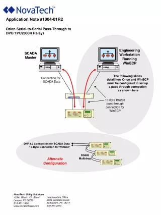
SCADA • SCADA stands for Supervisory Control and Data Acquisition. SCADA refers to a system that collects data from various sensors at a factory, plant or in other remote locations and then sends this data to a central computer which then manages and controls the data. • The feedback control loop passes through the remote terminal unit(RTU) or Prgrammable logic controller (PLC), while the SCADA system monitors the overall performance. • For example: • A PLC may control the flow of cooling water through part of an industrial process, but the SCADAsystem may allow operators to change the set points for the flow, and enable alarm conditions, such as loss of flow and high temperature, to be displayed and recorded. • Most essentially the SCADA system consists of three fundamental components (i.e. Master station (MS) or Central Monitoring System (CMS), Communication link and RTU or PLC). • A Central Monitoring System (CMS), contained within the plant and one or more Remote Stations. The CMS houses the Control Server and the communications routers via a peer-to-peer network. The CMS collects and logs information gathered by the remote stations and generates necessary actions for events detected. A remote station consists of either a Remote Terminal Unit (RTU) or a • Programmable Logic Controller (PLC) which controls actuators and monitors sensors.
Typically, remote stations have the added capability to be interfaced by field operators via hand held devices to perform diagnostic and repair operations. The communications network is the medium for transporting information between remote stations and the MS. This is performed using telephone line, cable, or radio frequency. If the remote site is too isolated to be reached via direct radio signal, a radio repeater is used to link the site. Simulation tools used to aid the operator in preventing disturbances. Simulation is used when the system which is to be analyse or design is complex to use analytical techniques (like aerodynamics). Simulation models can be descriptive and physical. Simulation models that are formulated called descriptive models. Physical models mostly are time-discrete showing the act and interact of entities of a system. These models can be built after many steps involving computer programs. The state of the system changes as a consequence of events in the system . These events are considered to occur at discrete times; models are called discrete event simulation models. Simulation languages Most well-known simulation languages are GASP IV, GPSS and SIMSCRIPT II.1
The process can be Industrial: include those of manufacturing, production, power generation, fabrication, and refining, Infrastructure : include water treatment and distribution, wastewater collection and treatment, oil and gas pipelines, electrical power transmission and distribution, and large communication systems. Facility based : including buildings, airports, ships, and space stations. They monitor and control HVAC, access, and energy consumption. HVAC "heating, ventilating, and air conditioning" is sometimes referred to as climate control Little More About SCADA A SCADA system manages electricity distribution by collecting data from, and issuing commands to, geographically remote field control stations from a centralized location. In the Oil and Gas industry, refining and processing facilities use distributed control systems (DCS) while holding facilities and distribution systems utilize SCADA technology. The water supply infrastructure utilizes DCS for the processing operations but use SCADA technology for distribution operations. A waste treatment plant runs similar to that of the water supply infrastructure.
Suppose you have a simple electrical circuit consisting of a switch and a light. Like this This circuit allows an operator to watch the light ( ) and know whether the switch is open or closed. The switch may indicate that a motor is running or stopped, or whether a door is open or closed, or even whether there has been a fault or the equipment is working. So far there is nothing special about this. But now imagine that the switch and the lamp were 100 kilometres apart. Obviously we couldn't have an electrical circuit this large, and it would now be a problem involving communications equipment Now complicate the problem a bit further. Imagine we had 2000 such circuits. We could not afford 2000 communications circuits. However someone found that we could use one communications circuit by sharing it. First we send the status (open/closed or 0/1) of the first circuit. Then we send the status of the second circuit, and so on. We need to indicate which circuit the status applies to when we send the data. The poor operator at the other end still has a problem. He has to watch all 2000 circuits. To simplify his task, we could use a computer. The computer would monitor all circuits, and tell the operator when he needs to look at a particular circuit. The computer will be told what the normal state of the circuit is and what state is an "alarm". It monitors all circuits, and informs the operator when any circuit goes into alarm. Simply called SCADA.
Mimic board Breaker Mechanism Analog meters VT CT Transducer Protective relay RTU Station computer Central control (SCADA) Monitoring & Control of local system using RTU: Automatic functions for local control performed by regulators, as well as sequence control performed by relays are integrated as software functions in the RTU.
One of key processes of SCADA is the ability to monitor an entire system in real time (run with relatively little human intervention). This is facilitated by data acquisitions including meter reading, checking statuses of sensors, etc. The SCADA software is a graphical package using a Window NT Operation System. The system, manufactured by Power Measurement Ltd (PML), provides the programming necessary to incorporate actual AutoCAD campus maps and diagrams, and to display real time information on top of the graphic background.
TECHNICAL FUNCTIONS OF SCADA: The SCADA system provides the following functions: Data acquisition: The basic information of the power system collected is called the Data Acquisition. The data is collected by means of CTs, PTs and transducers. It provides the telemetry measurement and status indication to the operator. Supervisory control: It enables the operator to remotely control the devices. For example open and close of the circuit breaker. Tagging: It prevents the device from unauthorized operation. Means it authorizes the device to perform the specific operation. Alarms: It informs the operator about the unnecessary events and undesired conditions. Logging (Recording): It logs all the operating entry, all alarms and other information. In other words it keeps the record of all the events. Load shading: It provides both the automatic and manual control tripping of load during the emergency. Trending: It plots the measurement on the selected time scale.
ESSENTIAL FEATURES OF SCADA: The simple layout of the SCADA system with its essential features is shown below in the fig: The SCADA system enables the operator to attain the complete knowledge of the system in a single room by means of display. Almost all the SCADA systems are computer based (Digital computer). This computer is located in the master unit. The master unit is the heart of the SCADA system, it comprises many of the i/p and o/p equipments to receive and send the control message from and to the RTU.
All the data of operations of RTU are transmitted to the master control unit and after collecting the information the data are feed back to the RTU. Also master unit consists of several modems which are used to convert the digital into analog or analog into digital message depending upon the requirement. The received information of the master unit is displayed on VDU and then is printed for permanent record. In addition the SCADA system also comprises some more peripheral equipment such as control console, VDU, Alarms, Printers, D/A converter and Recording instruments. Visual Display Unit (VDU) replaces mimic board to represent one line diagram, tabular display, bar charts, curves and event lists and used for entering commands to system. Modern system includes the color display which is used to distinguish b/w the different voltage levels. Also different colors differentiate the operator to understand the open and close of CB, also the flashing indication can be made which determines the change of the state of any device. The audible alarms can be used to alert the operator from the fault or condition. The printers are used to have the permanent records of the events. The D/A converter are used to convert the digital information into the analog information, and then the information is supplied to the indicating or the recording instruments. The recording instruments are used to store the data of each remote station unit.
FUNCTIONAL DIAGRAM OF SCADA: The functional diagram of SCADA consists of several parts such as Data base, Data acquisition, Main machine interface and application program etc, are shown below in the fig:
Data acquisition is the function of the SCADA which is required to perform the following functions: • It is used to read the power system data from 100-250 RTU into the control center. • It detects and handle the error conditions of RTU and communication link as well as. • It can be used to check the limits such as high/low operating limit, thermal limits, and safe handling limits. • It can be used to convert the analog data into the binary data. • It stores only the error free data in the data b/c erroneous data causes the failure of program. • It can interface with the data base manager, which generated the data address where data can be stored in data base. • It completes all above tasks in less than 2 seconds. • Typically data acquisition is implemented by the master station, software, and computer. The software consists of hundreds of different programs; at the same time these program needs access to describe the structure and state of the power system. Therefore the data base plays an important and central role in control system design. Thus the SCADA system requires an efficient and effective data base, data acquisition and main machine interface.
Data base as the name implies is base for all the functions (i.e. data acquisition, main machine interface and application program). The primary object of the data base is to provide a well defined processing for several functions. Data base is repertory for all power system dynamic data, common data, user program and manually entered variables from operator console and network data such as historical files and record of data. It physically resides within the computer system. The data base in the SCADA system provides the following advantages: • It provides organized structure of data expressed in file. • It stores the data with very little space require. Also it provides the flexibility in the selection of storage medium. • It provides the discrimination b/w data and program or b/w two programs. • It provides a well defined expansion of software system. • A SCADA system includes a user interface, usually called Human Machine Interface (HMI). The HMI of a SCADA system is where data is processed and presented to be viewed and monitored by a human operator. This interface usually includes controls where the individual can interface with the SCADA system. • Usually RTU's or PLC's will run a pre programmed process, but monitoring each of them individually can be difficult, because they are spread out over the system, HMI's are an easy way to standardize the facilitation of monitoring multiple RTU's or PLC's (programmable logic controllers). • HMI's can also be linked to a database, which can use data gathered from PLC's or RTU's to provide graphs on trends, logistic info, schematics for a specific sensor or machine or even make troubleshooting guides accessible.
Interesting, right? This is just a sneak preview of the full presentation. We hope you like it! To see the rest of it, just click here to view it in full on PowerShow.com. Then, if you’d like, you can also log in to PowerShow.com to download the entire presentation for free.