Download
1 / 112
1.12k likes | 1.13k Views
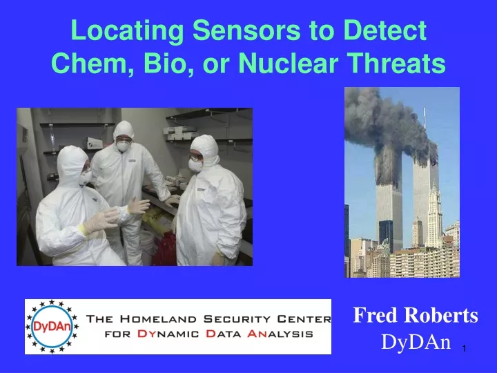
Locating Sensors to Detect Chem, Bio, or Nuclear Threats. Fred Roberts DyDAn. Sensors are finding many uses in homeland security. We place sensors in buildings, on bridges, at border crossings, and even on uniforms of police. They sense radiation, dangerous chemicals, biological agents, etc.

E N D
Locating Sensors to Detect Chem, Bio, or Nuclear Threats Fred Roberts DyDAn
Sensors are finding many uses in homeland security. We place sensors in buildings, on bridges, at border crossings, and even on uniforms of police. They sense radiation, dangerous chemicals, biological agents, etc.
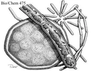
The Bioterrorism Sensor Location Problem Great concerns about deliberate release of disease-causing pathogens has caused us to Worry about “bioterrorism.” anthrax
Early warning is critical in defense against terrorism • This is a crucial factor underlying the government’s plans to place networks of sensors/detectors to warn of a bioterrorist attack The BASIS System – Salt Lake City
Types of Sensor Problems • I first got involved in sensor placement for biological attacks when I was approached by the Defense Threat Reduction Agency. • I ended up learning a lot about the problem from the Institute for Defense Analyses. • And from the NYC Department of Health • Similar issues arise in placing sensors to protect against or give early warning about attacks with chemical or nuclear weapons. • Or attacks on our networks: communication, financial, etc.
Types of Sensor Problems • Similar sensor placement problems arise in applications in: • Civil engineering: monitoring temperature, humidity, structural stability in a building, bridge, etc. • Manufacturing • Fault detection in distributed or multiprocessor computer systems
Locating Sensors is not Easy • Sensors are expensive • How do we select them and where do we place them to maximize “coverage,” expedite an alarm, and keep the cost down? • Approaches that improve upon existing, ad hoc location methods could save countless lives in the case of an attack and also moneyin capital and operational costs.
Two Fundamental Problems • Sensor Location Problem • Choose an appropriate mix of kinds of sensors • decide where to locate them for best protection and early warning
Two Fundamental Problems • Pattern Interpretation Problem: When sensors set off an alarm, help public health decision makers decide • Has an attack taken place? • What additional monitoring is needed? • What was its extent and location? • What is an appropriate response?
The SLP: What is a Measure of Success of a Solution? • A modeling problem. • Needs to be made precise. • Many possible formulations. • Good explorations for your students.
The SLP: What is a Measure of Success of a Solution? • Identify and ameliorate false alarms. • Defending against a “worst case” attack or an “average case” attack. • Minimize time to first alarm? (Worst case? (Average case?) • Maximize “coverage” of the area. • Minimize geographical area not covered • Minimize size of population not covered • Minimize probability of missing an attack
The SLP: What is a Measure of Success of a Solution? • Cost: Given a mix of available sensors and a fixed budget, what mix will best accomplish our other goals?
The SLP: What is a Measure of Success of a Solution? • It’s hard to separate the goals. • Even a small number of sensors might detect an attack if there is no constraint on time to alarm. • Without budgetary restrictions, a lot more can be accomplished.
The Sensor Location Problem • Approach is to develop new algorithmic methods. • Developing new algorithms involves fundamental mathematical analysis. • Analyzing how efficient algorithms are involves fundamental mathematical methods. • Implementing the algorithms on a computer is often a separate problem – which needs to go hand in hand with the basic mathematics of algorithm development.
Greedy Algorithms • Find the “most important” location to place a sensor first and locate a sensor there. • What things could “most important” mean? • Find second-most important location. • Etc. • Builds on earlier mathematical work at Institute for Defense Analyses (Grotte, Platt) • “Steepest ascent approach.’’ • No guarantee of “optimal” or best solution. • In practice, gets pretty close to optimal solution.
Algorithmic Approaches II : Variants of Classic Facility Location Theory Methods
Location Theory • Old problem in Operations research: Where to locate facilities (fire houses, garbage dumps, etc.) to best serve “users” • Often deal with a network with vertices, edges, and distances along edges • Users u1, u2, …, un arelocated at vertices • One approach: locate the facility at vertex x chosen so that sum of distances to users is minimized. • Minimize:
1 a f 1 1 e b 1 1 c d 1 Location Theory: A Network 1’s represent distances along edges Vertices are places for users or facilities
1 a f 1 1 e b 1 1 c d 1 Location Theory: A Network 1’s represent distances along edges d(x,y) = length of shortest route from x to y So, d(a,c) = 2.
1 a f 1 1 e b 1 1 c d 1 u1 u2 u3 Given users at u1, u2, u3, where do we place a facility to minimize the sum of distances to the users?
1 a f 1 1 e b 1 1 c d 1 u1 u2 u3 x=a: d(x,ui)=1+1+2=4 x=b: d(x,ui)=2+0+1=3 x=c: d(x,ui)=3+1+0=4 x=d: d(x,ui)=2+2+1=5 x=e: d(x,ui)=1+3+2=6 x=f: d(x,ui)=0+2+3=5 x=b is optimal
Location Theory • Users u1, u2, …, un arelocated at vertices • Alternative approach: Locate the facility at vertex x chosen so that maximum distance to one of the users is minimized.
1 a f 1 1 e b 1 1 c d 1 u1 u2 u3 Given users at u1, u2, u3, where do we place a facility to minimize the maximum distance a user has to travel to get to the facility?
1 a f 1 1 e b 1 1 c d 1 u1 u2 u3 x = a: maxid(ui,x) = 2 x = b: maxid(ui,b) = 2 x = c: maxid(ui,c) = 3 x = d: maxid(ui,d) = 2 x = e: maxid(ui,e) = 3 x = f: maxid(ui,f) = 3 There are three optimal solutions: a, b, d
Variants of Classic Facility Location Theory Methods: Complications • We don’t have a network with vertices and edges; we have points in a city • Sensors can only be at certain locations (size, weight, power source, hiding place) • We need to place more than one sensor • Instead of “users,” we have places where potential attacks take place. • Potential attacks take place with certain probabilities. • Wind, buildings, mountains, etc. add complications.
The Pattern Interpretation Problem (PIP) • It will be up to the Decision Maker to decide how to respond to an alarm from the sensor network.
Approaching the PIP: Minimizing False Alarms One approach: Redundancy. • Could require two or more sensors to make a detection before an alarm is considered confirmed • Could require same sensor to register two alarms: Biosensor “Portal Shield” requires two positives for the same agent during a specific time period.
Approaching the PIP: Minimizing False Alarms • Could place two or more sensors at or near the same location. Require two proximate sensors to give off an alarm before we consider it confirmed. • Redundancy has drawbacks: cost, delay in confirming an alarm. • We need mathematical methods to analyze the tradeoff between lowered false alarm rate and extra cost/delay
Sensor Placement in Networks • From now on, we will concentrate on networks or graphs. • G = (V,E) = graph; V = vertices, E = edges • Assume all edges have distance 1 • Limit to “attacks” on vertices • Assume detectors can only be placed at vertices • Two goals: • Detection: Detect that an attack on a vertex has taken place • Identification: Identify where the attack took place
Sensor Placement in Networks (Joint work with David L. Roberts) • Assume that a detector can detect an attack up to distance r away. • We often think of distance = time. • Assume that there are no errors in detection: If there is an attack up to distance r away, the detector will detect it with 100% certainty. • Nr[x] = set of all vertices in V to which there is a path in the graph of length at most r from x. (r-neighborhood of x)
a f e b c d Sensor Placement in Networks • N2(c) = ? • N2(c) = {c, b, d, a, e}
Sensor Placement in Networks • Let D be the set of vertices where we place a detector. • Let Dr(x) = Nr(x) D
a f e b c d Sensor Placement in Networks D = {a, b, f} D2(d) = ? D2(d) = {b, f}
Sensor Placement in Networks • Detection: D is an r-dominating set in G if for every vertex x of G, Dr(x) . • That is, for all x, there is a path of length at most r from x to some y in D.
a f e b c d Sensor Placement in Networks D = {a, b, f} D is a 2-dominating set. It is not a 1-dominating set.
Sensor Placement in Networks • Unique Identification: D is an r-identifying code(r-IC) in G if it is an r-dominating set and if, whenever x y are vertices, Dr(x) Dr(y). • In an r-IC, the set of detectors activated by an attack provides a unique signature that allows us to determine where the attack took place. • We shall look for the smallest d so that there is an r-IC of d vertices
a f e b c d Sensor Placement in Networks D = {a, b, f} D is a 2-dominating set. Is D a 2-IC?
a f e b c d Sensor Placement in Networks D = {a, b, f} D2(a) = {a, b, f} D2(b) = {a, b, f} So: D is not a 2-IC
a f e b c d Sensor Placement in Networks Can you find a 2-IC?
a f e b c d Sensor Placement in Networks Can you find a 2-IC? D = {b, d, f} is not a 2-IC. Why?
a f e b c d Sensor Placement in Networks Can you find a 2-IC? D = {b, d, f} is not a 2-IC. Why? D2(b) = D2(d)
a f e b c d Sensor Placement in Networks D = {a, b, c, d, e} is a 2-IC. D2(a) = {a, b, c, e} D2(b) = {a, b, c, d} D2(c) = {a, b, c, d, e} D2(d) = {b, c, d, e} D2(e) ={a, c, d, e} D2(f) = {a, b, d, e}
a f e b c d Sensor Placement in Networks D = {a, b, c, d, e} is a 2-IC. Can you find a smaller one?
a f e b c d Sensor Placement in Networks Can you find a smaller one? Answer: No. But the proof is a bit complicated.
Sensor Placement in Networks In general, the problem of finding optimal r-ICs is difficult in a precise sense: It is NP-complete in general and for many special classes of graphs
Sensor Placement in Networks: 1-Identifying Codes Let us concentrate first on 1-IC’s. • Many network structures have been studied: • Paths and cycles • Binary cubes and nonbinary cubes and hypercubes and meshes (of interest in CS applications) • Trees • Square lattices • Hexagonal and triangular grids • Complete multipartite graphs • Planar and outerplanar graphs


![Welcome to CHEM BIO 3OA3! Bio-organic Chemistry [OLD CHEM 3FF3]](https://cdn3.slideserve.com/6585744/welcome-to-chem-bio-3oa3-bio-organic-chemistry-old-chem-3ff3-dt.jpg)