Download
1 / 16
170 likes | 392 Views
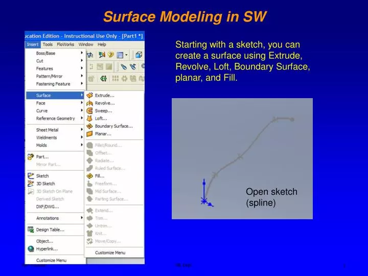
Surface Modeling in SW. Starting with a sketch, you can create a surface using Extrude, Revolve, Loft, Boundary Surface, planar, and Fill. Open sketch (spline). Axis of rotation. Revolved surface. Extruded surface. Surface Modeling in SW – Ruled Surfaces. Profile. Extrusion direction.

E N D
Surface Modeling in SW Starting with a sketch, you can create a surface using Extrude, Revolve, Loft, Boundary Surface, planar, and Fill. Open sketch (spline) ME Dept.
Axis of rotation Revolved surface Extruded surface Surface Modeling in SW – Ruled Surfaces Profile Extrusion direction ME Dept.
Swept surface using a Guide Surface Modeling in SW Guide ME Dept.
Loft surface, no guide curve Loft surface using two guide curves. Surface Modeling in SW - Ruled Surfaces Guide 2 Guide 1 ME Dept.
Surface Modeling in SW- Boundary Surface Four curves defining the boundary of the surface, Coon’s surface Make sure all curves are intersecting, then select curves for directions 1 and 2 Sketch5, Direction 1 Sketch1, Direction 2 Sketch2, Direction 2 Open loop 3D sketch, Direction 1 ME Dept.
Boundary surface Direction 2 Direction 2 Direction 2 The order of direction has no effect on the surface shape Direction 2 Surface Modeling in SW- Boundary Surface ME Dept.
Surface Modeling in SW- Boundary Surface Direction 1 Direction 1 ME Dept.
Direction 1 Direction 2 Direction 2 Direction 1 Direction 1 Single curve to a point in one direction Surface Modeling in SW- Boundary Surface Boundary Surface option using profiles and directions. This results in the same surface as Loft, smoother surface appearance. ME Dept.
Surface Modeling in SW- Fill Surface ME Dept.
Through Curves option This command creates a sheet or solid body through a set of up to 150 section strings. A section string can consist of a single object or multiple objects, and each object can be a curve, a solid edge, or a solid face. Through Curves is similar to a Ruled Surface, except that you can specify more than two section strings. Surface Modeling in Unigraphics (NX) ME Dept.
Surface Modeling in Unigraphics (NX) Desired curve sections ME Dept.
Surface Modeling in Unigraphics (NX) Through Curve option This command creates a body from sets of primary and cross strings. Strings in each set must be roughly parallel to each other and non-intersecting. Primary strings must be roughly perpendicular to crossing strings Primary strings Cross strings ME Dept.
Surface Modeling in Unigraphics (NX) N-Sided Surface option This option lets you build a surface with an unrestricted number of curves or edges that form a simple, open or closed loop, and assign continuity to outside faces. You can remove holes in surfaces that are not four-sided. Shape control options are available to refine sharpness at center point, while maintaining continuity constraints. Sample of a Multiple Triangular Patch Surface ME Dept.
Surface Modeling in Unigraphics (NX) You can use the Section option to construct bodies through sections that you define using conic construction techniques. You can think of a section free form feature as an infinite family of section curves lying in prescribed planes, starting and ending on, and passing through, certain selected control curves. Additionally, the system obtains conic end slopes directly from the control curves, and uses a continuous 2D conic shape parameter to vary the fullness of the sections along the body. A typical application for using a section free form feature would be in the design of an aircraft fuselage. The control curves would run along the top and along the side of the fuselage, and the section curves would lie in planes perpendicular to the centerline. Another example would be in creating an automobile body panel design, where you know the start and end edges and slopes, and a smooth curve without inflections is required ME Dept.
Surface Modeling in Unigraphics (NX) ME Dept.
Surface Modeling in Unigraphics (NX) Use the Studio Surface command to create swept or lofted surfaces from a network of section strings, or a network of section strings and up to three guide strings. Three section strings and resulting studio surface Section string (1), guide strings (2), and resulting studio surface You can modify a Studio Surface without rebuilding it by adding, removing, reordering, or swapping section and guide strings. Studio Surface also lets you specify constraining faces and continuity, edit surface alignment points, and control the transitions between surface sections. ME Dept.