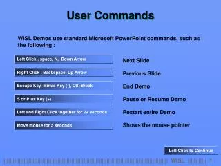
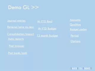
Download
1 / 16
160 likes | 233 Views
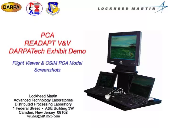
PCA READAPT V&V DARPATech Exhibit Demo. Flight Viewer & CSIM PCA Model Screenshots. Lockheed Martin Advanced Technology Laboratories Distributed Processing Laboratory 1 Federal Street • A&E Building 3W Camden, New Jersey 08102 mjunod@atl.lmco.com.

E N D
PCAREADAPT V&VDARPATech Exhibit Demo Flight Viewer & CSIM PCA Model Screenshots Lockheed Martin Advanced Technology Laboratories Distributed Processing Laboratory 1 Federal Street • A&E Building 3W Camden, New Jersey 08102 mjunod@atl.lmco.com
Flight Simulator provides context display CSIM simulates PCA enabled route planner CSIM controls CDU on Flight Simulator MaCS monitors route planner execution & controls PCA & algorithm adaptation CSIM MaCS Monitoring script configure event def. Integrator state records interface objects PCA V&V Demo Setup Laptop 1 - CSIM / MaCS Display Laptop 2 - Flight Viewer Display withRoute Planner Overlay Route Planning Algorithm Target Set (Endpoint) Planning Horizon Grid Size C(r,r+dr) Cardinality (Direction) Incremental Cost
CSIM Display(CSIM Model of PCA TRIPS Like Architecture) System State and Task Flow PCA Virtual Processor State and Activity Mission Assignment Total active processor count display Threat Avoidance Stream Processors indicated byfilled boxes Comms GP Processors indicated by (non-Red) outlined boxes Flight Control Imaging Threaded Processors indicated by REDoutlined boxes Route Planning Dynamic bar chart indicating total active processors, active stream processors active GP processors and active threaded processors Self Test and MaCS MaCS messages and status Mission status RADAR Tasks
Mission Status Indicator Flight Route Navigation Waypoints Threat Sites Aerial View Flight Viewer Display(UAV Flying in Auto-Pilot Mode)
Flight Route Threat Site UAV Scenario Start(4 Initial Threat Sites & Pre-Planned Route)
New Threat Cost Matrix Grid Area New Threat Inserted(New Cost Matrix Grid Area)
Route Planning Active Route Replan(Threaded Route Planning Processes in RED)
Routed Around Threat Rerouted Around New Threat
New Threat Cost Matrix Grid Area (Dense) New Threat Inserted w/ Targeting(Dense Cost Matrix Grid)
Route Planning Active Flight Control Active Competing Resources Requirements Violation Detected MaCS Detected Req. Violation(Flight Control competing with Route Replan)
Cost Matrix Grid Adjusted (Less Dense) Reduction of Cost Matrix Density(MaCS Detected Run-Time Requirements Violation)
Routed Around Threat Rerouted Around 2nd New Threat(Factored in mountain elevation for new route)