Download
1 / 42
420 likes | 423 Views
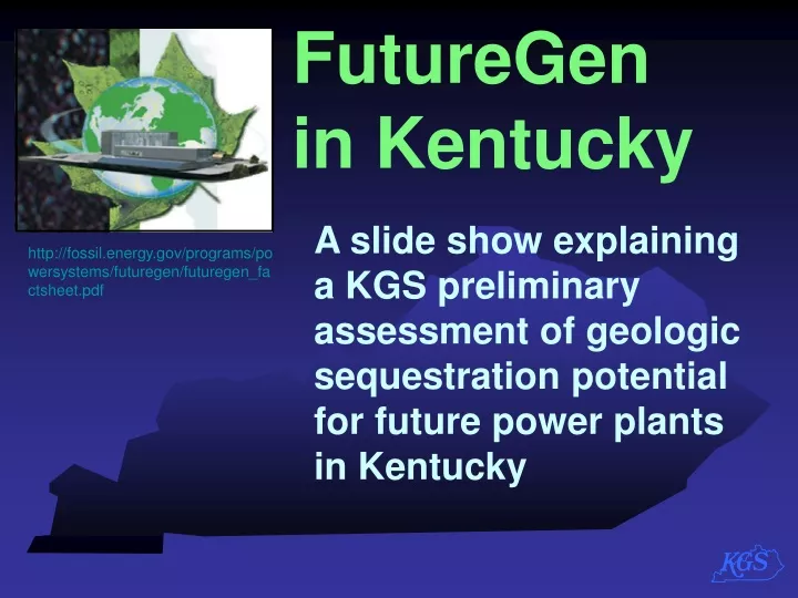
FutureGen in Kentucky. A slide show explaining a KGS preliminary assessment of geologic sequestration potential for future power plants in Kentucky. http://fossil.energy.gov/programs/powersystems/futuregen/futuregen_factsheet.pdf. FutureGen.

E N D
FutureGen in Kentucky A slide show explaining a KGS preliminary assessment of geologic sequestration potential for future power plants in Kentucky http://fossil.energy.gov/programs/powersystems/futuregen/futuregen_factsheet.pdf
FutureGen is a DOE program to design a power plant that will integrate advanced coal gasification to produce hydrogen and electric power with CO2 capture and storage (also called sequestration) http://fossil.energy.gov/programs/powersystems/futuregen/futuregen_factsheet.pdf
FutureGen in Kentucky Geologic sequestration potential http://fossil.energy.gov/programs/powersystems/futuregen/futuregen_factsheet.pdf • Why FutureGen? Concerns about climate change resulting in a need to reduce CO2emissions • FutureGen will be a near-zero emissions power plant funded by DOE and industry • FutureGen will incorporate geologic carbon sequestration to reduce CO2
Limiting future carbon emissions from power plants is a critical component of DOE- sponsored energy research including FutureGen. • “the captured CO2…would then be permanently sequestered in a geologic formation.” • Validating the integrated operation of gasification technology • Proving effectiveness, permanence, and safety of sequestration in a geologic formation From the DOE FutureGen fact sheet: Major goals include:
The Kentucky Geological Survey is part of three Phase II partnerships Midwest Regional Carbon Sequestration Partnership Midwest (Illinois Basin) Geological Sequestration Consortium Southeast Regional Carbon Sequestration Partnership More info at DOE’s www.fossil.energy.gov/programs/sequestration/
Multiple options at different locations Power plant Pipeline • Unmineable coals • Organic-richshales • Depleted oil and gas reservoirs • Deep saline aquifers After Harper (2004) Geologic carbon sequestration possibilities • Regional DOE partnerships are assessing several types of geologic reservoirs • Enhanced oil and gas recovery may be possible for unmineable coals, organic-rich shales, and depleted oil and gas reservoirs
Geologic carbon sequestration possibilities FutureGen Unmineable Coal Beds Injection into unmineable coal beds might allow secondary recovery of methane in some (not all) areas Images modified from Midwest Regional Carbon Sequestration Partnership (2005) http://198.87.0.58/Geologic.aspx
Geologic carbon sequestration possibilities FutureGen Oil and Gas Reservoirs Injection into depleted oil or gas reservoirs might allow secondary recovery of oil or gas Images modified from Midwest Regional Carbon Sequestration Partnership (2005) http://198.87.0.58/Geologic.aspx
Geologic carbon sequestration possibilities FutureGen Deep Saline Aquifers Injection into deep saline aquifers offers possibility of storage without negating a potential resource Images modified from Midwest Regional Carbon Sequestration Partnership (2005) http://198.87.0.58/Geologic.aspx
Geologic carbon sequestration possibilities Minimal transport distance Minimal transport distance Multiple reservoirs Power plant Pipeline Enough depth to minimize leakage and to keep CO2 in supercritical phase Coals + Oil and gas reservoirs + Saline aquifers After Harper (2004) Optimal sites might have multiple reservoirs (stacked or at several locations) at depth, within some distance of the plant based on the transport costs of CO2
Geologic carbon sequestration possibilities FutureGen Preliminary requirements: • Large storage volume • For a FutureGen–type plant,DOE estimates1 million tons CO2 /year for 30 years = 30 million tons CO2 • Could be one large or multiple reservoirs Image modified from Midwest Regional Carbon Sequestration Partnership (2005) http://198.87.0.58/Geologic.aspx
Geologic carbon sequestration possibilities FutureGen Preliminary requirements: • Depth (> 2,500’) for existing depleted oil and gas reservoirs • In our area, this is the depth needed to keep any injected CO2 in liquid form (miscible)* • Injection into unmineable coals could be shallower because of a different sequestration mechanism Image modified from Midwest Regional Carbon Sequestration Partnership (2005) http://198.87.0.58/Geologic.aspx * Greater depth also provides more seals to prevent leakage
Geologic carbon sequestration possibilities FutureGen Preliminary requirements: • Proximity to existing energy infrastructure and likely a waterway • Most existing KY power plants are near large rivers Image modified from Midwest Regional Carbon Sequestration Partnership (2005) http://198.87.0.58/Geologic.aspx
Most along rivers Existing and proposed power plants Existing power plants Proposed plants • Power plant siting involves many non-geologic decisions • By using existing plant locations to define the study area we incorporated those decisions with the geologic assessment.
Existing and proposed power plant counties Existing power plants Proposed plants • Future power plants are likely to have at least the existing requirements relative to water. • Study area limited to counties with known and proposed plants, similar water supplies, or large coal resources* *these might not have water needs for some types of plants
Existing and proposed power plant counties Existing power plants Proposed plants • Areas might include a 25-mile radius around existing and proposed plants as examples of hypothetical transport areas around each • Circles show possibility for pipeline transport
Existing and proposed power plant counties NATCARB Pipeline cost calculator Result Cost is: $2,860,898 Distance is: 28 miles The reason for examining the radius around some areas is that pipeline transport to a sequestration site might be needed. http://drysdale.kgs.ku.edu/natcarb/midflash/natcarb_new_content.html
Seismicity Magnitude Peak ground acceleration >0.3g 3.0 4.0 5.0 + • Seismic potential is greatest in far western Kentucky • Seismic potential may be concern for building future large, Federally funded (or co-funded) construction projects • Faults (red lines) will also need to be considered (not for seismic potential but for reservoir leakage and seal potential)
Kentucky “unmineable” coal potential 2003 Coal production (Mt) 15+ No production in study area 10-15 5-10 1-5 0-1 • Kentucky has two coal fields (the Eastern Kentucky Coal Field and the Western Kentucky Coal Field) • Coal is mined at 1000 ft in western Kentucky • Coal is mined at depths beneath surface of more than 1000 ft in eastern Kentucky, but in some places that is still“above drainage”
Kentucky “unmineable” coal potential Areas with multiple deep coals below drainage Gray: Coals > 500 ft deep Red: Coals > 1,000 ft deep • Surface fracturing extends 400 to 500 feet beneath the surface, so potential coals would need to be at least 500 feet beneath drainage • Areas of coals at depth are smaller than the total area of the coal fields • Definition of “unmineable” is variable and will influence potential
Oil Gas Waterflood Known Kentucky oil and gas reservoirs Operating and abandoned oil and gas fields • Kentucky has hundreds of oil and gas fields • Not all are within the electric power infrastructure area • Not all fields are likely sequestration targets
Volumes >15 MM tons (20 fields) 2,500 ft or deeper Known Kentucky oil and gas reservoirs Fields with sufficient depth or volume • Known fields have demonstrated reservoir and trap properties • 9 have >30 MM tons estimated capacity for CO2 storage • Many of these fields are not abandoned
Known Kentucky oil and gas reservoirs Western KY Central KY Eastern KY Oil field (generalized) Gas field (generalized) 2,500 feet • Kentucky’s geology controls the depth of the known oil and gas fields. Major oil- and gas-bearing units are shallower than 2,500 feet in the central part of the state. • There are speculative possibilities deeper.
Red has most potential Blue has least potential Tan has no potential Additional potential oil and gas reservoirs Organic shales: a different type of potential CO2 reservoir • KGS is currently funded by DOE to investigate the potential of black (organic-rich) shales to adsorb CO2 as a sequestration mechanism • The black shales are widespread with large potential capacity • Not a proven CO2 sequestration reservoir; behaves like coals
Net Sand Thickness Red is thickest Blue is thinnest Tan is no sand Kentucky potential deep saline reservoirs Deep sands (saline aquifers) • DOE partnerships have shown that deep saline aquifers (mostly sandstone) have greatest potential for large storage volume • Possible cumulative thickness is > 800 ft in western KY • Limited well penetrations and reservoir data in KY
St. Peter Rock units beneath Kentucky “Vuggy” Copper Ridge Rose Run • Strata vary in characteristics • Some are known reservoirs • Some are potential reservoirs • Some are seals • Deep saline reservoirs shown with arrows Mt. Simon Rome sands Middle Run/ Four Sand Diagram from MRCSP research
Kentucky potential deep saline reservoirs Mount Simon Sandstone Isopach Map No Mt. Simon south of the Kentucky River and Rough Creek FZs • Based on ~20 wells • Potential for as much as 6 Bmt capacity
Kentucky potential deep saline reservoirs Thick, Porous Rome Sandstone Wedge ( up to 700’ thick) Contour Interval = 50 ft • Deep sands south of the Kentucky River Fault Zone
Kentucky potential deep saline reservoirs 150 ft contour interval Top Conasauga Structure Map • Possibility for closed structure traps in Rome Trough • Depth here 4,000 to 5,000 ft • Potential capacity 3.5 Bmt CO2
Paleozoic Precambrian Unconformity 3 4 4 S 4 1mi 5 Kentucky potential deep saline reservoirs Middle Run (“4 Sand”) Reservoir N S • “4 Sand” (4S) is a mappable seismic sequence • Reflection seismic will be needed for sequestration site evaluations and for monitoring after CO2 injection
Kentucky potential deep saline reservoirs Middle Run (“4 Sand”) Reservoir • 81 sq. mi. lens in Hart Co. • Averages 440 ft. thick • 7,000-9,500 feet depth • ~3 Bmt potential capacity • Are there other similar lenses? • Additional study needed N 0 0 0 0 100 ft contour interval
Assessment of carbon sequestration options along the power plant infrastructure areas Seismic concern area • Next we will compare the infrastructure area (in tan) to the number of known and speculative sequestration options by county
Outside study area Study area (no large oil and gas fields)* 1 option 2 options This area is away from large water supplies Areas with known oil and gas field options Known = • O&G fields >15 MM tons • O&G fields >2,500’ deep Areas with no “known” options do have potential/speculative options.
Outside study area Fewest (1) Most (6) Areas with known and possible/speculativegeologic options Based on: • O&G fields >15 MM tons • O&G fields >2,500’ deep • Coals below 1,000 ft • Number of deep sands • Potential in black shale • Other speculative reservoirs
Preliminary Summary • There are areas with multiple sequestration options in both eastern and western KY along existing river corridors or within coal fields for short fuel-transport distances • There are known and more speculative (but possible) reservoir options in the same regions
Preliminary Summary • All reservoirs would need further testing to determine reservoir characteristics (permeability, water chemistry, etc.) for reservoir modeling • Permitting and regulations for test (small quantity) and future large quantity CO2 injections will be important in determining the potential future application of this technology in Kentucky
Potentially, some of the best areas for sequestration in saline formations (at depth) near power plants Thin and/or shallow Best Good Thick, but deep Based on: • Thickness of Mt. Simon • Depth of Mt. Simon • Depth of vuggy Copper Ridge • Thickness of Rome Ss. • Depth of Rome Ss • St. Peter and Rose Run Ss • Thickness of Middle Run Ss • Depth of Middle Run Ss More explanation follows
Potentially, some of the best areas for sequestration in saline formations (at depth) near power plants Thin and/or shallow Best Good Thick, but deep • Best here, is the area in the river corridor that had the most options at optimal depths, i.e. moderately deep (5,000-8,000 ft) and thick (400-750 ft) Mt. Simon Sandstone and thin St. Peter (<60 ft) and Rose Run (<80 ft) at moderate depth (3,000-4,000 ft)
Potentially, some of the best areas for sequestration in saline formations (at depth) near power plants Thin and/or shallow Best Good Thick, but deep • Good here, are the areas in the infrastructure region that had some deep saline reservoir potential (but with fewer options, i.e. thinner, or deeper potential reservoirs) in combination with other known or speculative options
Final Summary • In terms of potential volume, deep saline reservoirs are likely the best option for large-scale, permanent CO2 storage • Several lie in central and eastern Kentucky on or near navigatible waterways • These reservoirs would require further testing to determine reservoir characteristics (permeability, water chemistry, etc.) for reservoir modeling http://fossil.energy.gov/programs/powersystems/futuregen/futuregen_factsheet.pdf
Acknowledgements • This presentation was developed by the Energy and Mineral Section of the Kentucky Geological Survey • Contributors: • Stephen F. Greb • Brandon C. Nuttall • James A. Drahovzal • James C. Cobb • Cortland F. Eble • John B. Hickman • Paul D. Lake • Thomas M. Parris • Michael P. Solis • Kathryn G. Takacs http://fossil.energy.gov/programs/powersystems/futuregen/futuregen_factsheet.pdf
For more information: • DOE Carbon SequestrationProgram www.fossil.energy.gov/programs/sequestration/ • DOE FutureGen Initiative • http://www.fossil.energy.gov/programs/powersystems/futuregen/index.html • MRCSP Partnership http://198.87.0.58/CarbonSequestration.aspx • MGSC (Illinois Basin) Partnership • DOE Carbon Sequestration Technology Roadmap and Program Plan for 2005 http://sequestration.org/ http://www.fossil.energy.gov/programs/sequestration/publications/programplans/2005/sequestration_roadmap_2005.pdf • SECARB Partnership http://www.secarbon.org/ • DOE Carbon Sequestration Technology Roadmap and Program Plan for 2005 http://cdiac2.esd.ornl.gov/index.html