Download
1 / 22
220 likes | 223 Views
service repair manual

E N D
Service Manual ST3000 Series Printed in Germany ●Revision Level A Order Number: 812557-006
TABLE OF CONTENT Printed in Germany I
TABLE OF CONTENT Table of Content MA – SAFETY Safety Symbols used in the Manual...................................... 3 General Maintenance and Repair Safety Notes ................... 3 Maintenance and Repair ................................................ 3 Before Leaving the Truck ................................................ 4 Before Carrying out Work on the Truck.......................... 4 Before Operating the Truck............................................. 4 Warnings and Labels on the Truck ........................................ 4 PAGE SER-NO. CUT.................. REV. ITD – INTRODUCTION General..................................................................................... 7 Operating Instructions .................................................... 7 Service Training .............................................................. 7 Ordering Spare Parts...................................................... 7 Using the Manual ............................................................ 7 Model-Number ......................................................................... 8 PAGE SER-N0. CUT REV. M1 – LUBRICATION AND ADJUSTMENT COMPONENT ACCESS ........................................................... 11 Lifting and Blocking................................................................ 13 Outriggers................................................................................ 14 Recommended Lubricants and Oils .............................. 15 Lubricants ................................................................... 15 Cold Store Trucks........................................................ 15 Truck Decommissioning.................................................. 15 Restoring the Truck to Service .............................................. 15 Maintenance ............................................................................ 19 Lubrication points and intervals ..................................... 19 Inspection and Maintenance Schedule ......................... 21 Casters ..................................................................................... 30 Torques .................................................................................... 31 PAGE SER-N0. CUT .................. REV. M2 – HYDRAULICS Hydraulic Symbols.................................................................. 35 Hydraulic Unit Removal.......................................................... 39 Hydraulic System ............................................................ 40 Operation......................................................................... 40 Raise (Refer to Illustration) ......................................... 40 Lower .......................................................................... 41 Hydraulic Reservoir Capacity......................................... 42 Changing the hydraulic oil and hydraulic filter ............ 42 MOTOR & PUMP ASSEMBLY ........................................ 44 HYDRAULIC LINES AND FITTINGS .......................... 44 General Rules for Hydraulic Lines and Fittings ........................................................................ 44 CIRCUIT BLEEDING .................................................. 45 DRIFT TEST ............................................................... 45 Proportional function:................................................ 45 REMOVAL ....................................................................... 45 MOTOR............................................................................ 46 PUMP .............................................................................. 46 After replacing pump:................................................ 46 Replacing the relief valve ............................................... 47 Relief valve setting.......................................................... 47 Relief valve test and setting........................................ 47 HYDRAULIC TROUBLESHOOTING CHART ................ 48 PAGE SER-N0. CUT .................. REV. ST3000 10/2004 • Printed in Germany MS-IDX-3130 III
TABLE OF CONTENT M3 – DRIVE UNIT Gear Unit .................................................................................. 51 Drive unit, general................................................................... 52 Drive unit removal ........................................................... 52 Drive motor removal ....................................................... 52 Motor disassembly .......................................................... 53 Motor assembly............................................................... 53 Drive motor assembly ..................................................... 55 Gear unit disassembly .................................................... 56 General ....................................................................... 56 Preparation ................................................................. 56 Draining the oil............................................................ 56 Drive unit removal ....................................................... 56 Gear unit cover removal.............................................. 56 Gear unit disassembly ................................................ 57 Gear unit assembly ..................................................... 57 Gear unit cover installation ......................................... 59 Adding Oil ................................................................... 59 Drive unit installation ...................................................... 59 PAGE SER-N0. CUT .................. REV. M4 – ELEKTRICS Electrics - General .................................................................. 63 Wire Colour Codes.................................................................. 63 Abbreviations .......................................................................... 64 Electrical Symbols .................................................................. 67 Electrical Components ........................................................... 68 Traction Pod (POT, FS, RS)............................................ 68 Fast / Slow Travel Switch (HSS)..................................... 68 Safety Reverse Switch (SAS)......................................... 68 Brake Switch (BRS) ........................................................ 68 Override Switch (ORS) ................................................... 68 Raise / Lower Switches (RAS, LOS) ............................. 69 Limit Switch (LMS).......................................................... 69 Horn Switch (HNS) ......................................................... 69 Key Switch (KYS)............................................................ 69 Emergency Disconnect (BD).......................................... 69 Fuses (FU) ...................................................................... 69 PAGE SER-N0. CUT .................. REV. ?????? Thermal Switch (THS)......................................... 69 Hydraulic Control Module (HCM) ................................... 69 Unigage (BDI) ................................................................. 69 Integrated Charger.......................................................... 69 Plug Holder (PC)............................................................. 69 Drive motor (M1) ............................................................. 69 Hydraulic Motor (M2) ...................................................... 69 Main Contactor (Line/LC) ............................................... 70 Lift Contactor (P/P1+P2) ................................................ 70 Electromagnetic Brake (BRK) ........................................ 70 Terminal Board (TB) ....................................................... 70 Travel Alarm Driver (DR) ................................................ 70 Aux. Hydraulic Switch (SLS/SRS) .................................. 70 Remote Control Toggle Switch (ECS)............................ 70 Aux. Hydraulic Valves (SVA1/SVA2) .............................. 70 Horn (HN) ........................................................................ 70 Main Circuit Board (MAIN PCB)..................................... 70 Hydraulic Circuit Board (HYD PCB)............................... 70 Travel Alarm (ALM) ......................................................... 70 Receiver .......................................................................... 70 Transmitter....................................................................... 70 MS-IDX-3130 ST3000 10/2004 • Printed in Germany IV
TABLE OF CONTENT M4 – ELEKTRICS SEM0 Traction Controller........................................................ 74 General............................................................................ 74 Precautionary Measures............................................. 74 Functional Characteristics.............................................. 74 Speed control.............................................................. 74 Reduced speed ranges .............................................. 74 Downhill speed control................................................ 74 Regenerative braking.................................................. 74 Anti Roll Down Function ............................................. 75 Hourmeter................................................................... 75 Self-Diagnostic System............................................... 75 Monitored Circuits....................................................... 75 Safety Mechanisms......................................................... 75 Incorrect polarity ............................................................. 75 Wiring Errors............................................................... 75 Temperature protection............................................... 75 Start sequence ........................................................... 75 Protection rating.......................................................... 75 Maintenance.................................................................... 76 Replacing the SEM0 Traction Controller......................................................................... 77 Parameter Setting after Replacing the Traction Controller .................................................... 77 Preparatory Measures ................................................ 77 Adjustment .................................................................. 77 Status LED ...................................................................... 79 Programmer............................................................................. 80 General............................................................................ 80 Crown Handset P/N 793548 (Includes Cord) ........... 80 Operating SEM0 Controller Menu.......................................... 81 General............................................................................ 81 Menu structure............................................................ 81 Menu Functions .............................................................. 82 PARAMETER CHANGE.............................................. 82 TEST........................................................................... 82 ALARMS ..................................................................... 82 PROGRAM VACC ....................................................... 82 CONFIG ...................................................................... 82 Functions Menu, general................................................ 83 Parameter Change Menus ............................................. 84 Settings and Error Messages......................................... 85 Tester Menu..................................................................... 86 TESTER Menu ................................................................ 87 Alarms Menu ................................................................... 88 ALARMS Menu................................................................ 89 Calibrating the Traction Pod Potentiometer, PROGRAM VACC menu ................................................. 92 Preparatory Measures ................................................ 92 Calibration................................................................... 92 Config. Menu ................................................................... 93 CONFIG Menu ................................................................ 94 SET MODEL ............................................................... 94 SET OPTIONS............................................................ 94 ADJUSTMENTS ......................................................... 94 On Board Charger ................................................................... 95 General............................................................................ 95 Battery Charging Phases ............................................... 95 First Phase (I1) ........................................................... 95 PAGE SER-N0. CUT .................. REV. ST3000 10/2004 • Printed in Germany MS-IDX-3130 V
TABLE OF CONTENT M4 – ELEKTRICS Second Phase (P)....................................................... 95 Third Phase (U) .......................................................... 95 Fourth Phase (I2)........................................................ 95 End of Normal Charging ............................................. 96 Special Charging Phases ............................................... 96 Compensating Charge................................................ 96 Float Charge ............................................................... 96 Partial Charging .......................................................... 96 Charging Errors............................................................... 97 Green LED is not lit..................................................... 97 Possible Causes: ...................................................... 97 Green LED flashing .................................................... 97 Important Technical Data................................................ 98 Replacing the Charger ................................................... 98 Removal / Installation.................................................. 98 Traction Motor Maintenance .................................................. 99 Access to brushes .......................................................... 99 Maintenance.................................................................... 99 Armature ..................................................................... 99 Bearings...................................................................... 99 Pump Motor Maintenance ...................................................... 100 Access to brushes .......................................................... 100 Maintenance.................................................................... 100 Armature.......................................................................... 100 REPLACING PUMP MOTOR BRUSHES....................... 100 Contactors ............................................................................... 102 Inspection ........................................................................ 102 Contacts...................................................................... 102 Coils ............................................................................ 102 Springs........................................................................ 102 Servicing ......................................................................... 103 Dismantling ................................................................. 103 Assembly .................................................................... 103 Hydraulic Control Module (HCM)........................................... 104 Battery Discharge Indicator (BDI) ......................................... 105 OPERATION.................................................................... 105 General............................................................................ 106 Battery Discharge Indicator Setting (BDI) ..................... 106 Calibration for wet batteries ........................................... 107 TROUBLESHOOTING .................................................... 108 Traction Controller Safety Test ....................................... 109 PAGE SER-N0. CUT .................. REV. M5 – BRAKE Brake ........................................................................................ 113 Function........................................................................... 113 Disassembly .................................................................... 113 Assembly ......................................................................... 115 Air gap setting ................................................................. 115 Brake moment setting..................................................... 116 Brake test ........................................................................ 116 Definition of run-in/new rotor ...................................... 116 General Notes............................................................. 116 PAGE SER-N0. CUT .................. REV. M6 – DIRECTION Live ring bearing ..................................................................... 121 Disassembly .................................................................... 121 Assembly ......................................................................... 121 PAGE SER-N0. CUT .................. REV. MS-IDX-3130 ST3000 10/2004 • Printed in Germany VI
TABLE OF CONTENT M6 – DIRECTION Control handle return springs ............................................... 122 Adjustment ...................................................................... 122 Disassembly .................................................................... 122 Assembly ......................................................................... 122 Control Handle Grip ................................................................ 123 Main Components........................................................... 123 Hand grip component removal and assembly ..................... 124 Hand Grip Shells............................................................. 124 Upper and lower shell removal ................................... 124 Upper and lower shell assembly................................. 125 Switch Unit ...................................................................... 126 Disassembly ............................................................... 126 Switch unit assembly .................................................. 126 “Rabbit/Turtle” toggle switch........................................... 127 Disassembly ............................................................... 127 Assembly .................................................................... 127 Hydraulic PC board......................................................... 127 Disassembly ............................................................... 127 Assembly .................................................................... 127 Main PC Board Removal/Installation ............................. 128 Potentiometer .................................................................. 129 Disassembly ............................................................... 129 Assembly .................................................................... 130 Safety Reverse Switch.................................................... 130 Disassembly ............................................................... 130 Assembly .................................................................... 130 Horn switch ..................................................................... 131 Disassembly ............................................................... 131 Assembly .................................................................... 132 Hand Grip ........................................................................ 132 Disassembly ............................................................... 132 Assembly .................................................................... 132 PAGE SER-N0. CUT .................. REV. M7 – MAST Mast .......................................................................................... 135 General............................................................................ 135 Torque Requirements ................................................. 135 Lifting Gear Minimum Capacity................................... 135 TL Mast ....................................................................... 135 TT Mast....................................................................... 135 Mast Removal ................................................................. 135 Installation ....................................................................... 136 Fork Carriage Removal .................................................. 136 Fork Carriage Installation ............................................... 137 Fork Carriage Adjustment .............................................. 137 Mast Maintenance .......................................................... 138 Lubricating Roller Tracks............................................. 138 Mast shims.................................................................. 139 TL Mast Assembly .......................................................... 140 TT Mast Assembly .......................................................... 141 Lift chains ................................................................................ 142 General............................................................................ 142 Inspection ........................................................................ 142 Cleaning...................................................................... 142 Wear ........................................................................... 142 Freedom of Movement of Chain Links ........................ 143 Chain Tension ............................................................. 143 Chain Anchor and Pulleys .......................................... 144 PAGE SER-N0. CUT .................. REV. ST3000 10/2004 • Printed in Germany MS-IDX-3130 VII
TABLE OF CONTENT M7 – MAST PAGE SER-N0. CUT .................. REV. Worn Connection Plates ............................................. 144 Protruding or Turned Chain Pins................................. 144 Corrosion .................................................................... 144 Chain Lateral Wear ..................................................... 145 Uneven Chain Tension .............................................. 145 Misaligned Lift Components ..................................... 145 Lift Chain Lubrication...................................................... 146 Separating Lift Chains .................................................... 147 Tools and Equipment Required...................................... 147 Detachment ..................................................................... 147 Fork Tines ................................................................................ 148 General............................................................................ 148 Terms .......................................................................... 148 Fork Identification ....................................................... 148 Repairs ............................................................................ 148 Fork Inspection ............................................................... 148 Crack Inspection ......................................................... 148 Verticality Test ............................................................. 149 Fork Blade Warping .................................................... 149 Measuring the Fork Tip Width ........................................ 149 Fork Tine Height Difference ........................................... 149 Fork Stop ......................................................................... 149 Fork Blade Wear ............................................................. 150 M8 – CYLINDERS General............................................................................ 153 Safety when working on hydraulic systems ................ 153 General Instructions for Repairing Hydraulic Components.......................... 153 Rod Seal Assembly................................................................. 154 General............................................................................ 154 Large Rod Seal Assembly.............................................. 154 Small Seal Rod Assembly .............................................. 155 Rod Seal Assembly, Sealing Lip First............................ 156 Cylinders.................................................................................. 157 Mast Lift Cylinder ............................................................ 157 Seal Replacement ...................................................... 157 Installing Mast Lift Cylinders ....................................... 158 Carriage Cylinder............................................................ 159 Seal Replacement ...................................................... 159 Installing Carriage Cylinder ........................................ 160 Cylinder Bleeding and Flushing ..................................... 160 Bleeding — Mast Lift Cylinders................................... 160 Bleeding — Carriage Cylinder (if applicable).............. 160 Flushing – Mast Lift Cylinders and Carriage Cylinder (if applicable) .......................... 160 Drift Test ...................................................................... 161 Cylinder Shimming.......................................................... 161 Scondary Cylinder Shim ............................................. 161 Primary Cylinder Shim................................................ 161 PAGE SER-N0. CUT .................. REV. DIA – ELECTRICAL DIAGRAMS ST 3000 Standard .................................................................... 165 Overview.......................................................................... 165 Traction Controller - Semo Logic ................................... 166 Traction Controller - Semo Power Circuit ...................... 167 Power Unit Control Circuit .............................................. 168 PAGE SER-N0. CUT .................. REV. MS-IDX-3130 ST3000 10/2004 • Printed in Germany VIII
TABLE OF CONTENT DIA – ELECTRICAL DIAGRAMS Control Handle - Control Circuit..................................... 169 Hydraulic Control Module (HCM) ................................... 170 ST 3000 with Options.............................................................. 171 Overview.......................................................................... 171 Traction Controller - Semo Logic ................................... 172 Traction Controller - Semo Power Circuit ........................................................ 173 Power Unit - Control Circuit............................................ 174 Control Handle - Control Circuit..................................... 175 Hydraulic Control Module (HCM) - Travel Alarm and Flashing Beacon......176 Remote Control - Power Part ......................................... 177 Remote Control - Operator Platform.............................. 178 Wire Harness ........................................................................... 179 Control Handle Wiring .................................................... 180 Power Cables .................................................................. 181 PAGE SER-N0. CUT .................. REV. HYD – HYDRAULIC SCHEMATIC Hydraulic Schematic............................................................... 185 PAGE SER-N0. CUT .................. REV. ST3000 10/2004 • Printed in Germany MS-IDX-3130 IX
SAFETY Printed in Germany 1
SAFETY Safety Symbols used in the Manual General Maintenance and Repair Safety Notes To help guide you through the manual and to highlight parti- cular danger areas, we have used graphic illustrations: DANGER DANGER Read the safety notices in the truck Maintenance and Operator's Manuals. This symbol indicates life-threatening risks Failure to do so could result in severe or fatal injuries to maintenance personnel and/or other persons. ● Failure to comply with this notice may result in fatal injuries to yourself or other people. ● Motorised vehicles can be dangerous if maintenance and service are neglected. For this reason maintenance and inspections must be carried out at regular short intervals by trained personnel working to approved company guide- lines. WARNING This symbol indicates the risk of serious injury and/or serious material damage. Failure to comply with this notice may result in severe injuries to yourself or other people and/or serious material damage. ● DANGER Follow all national/local safety regula- tions applicable for maintenance work, e.g. for work on higher levels. CAUTION Failure to do so could result in severe or fatal injuries to maintenance personnel and/or other persons. ● This symbol indicates the risk of minor injury and/or minor material damage. Failure to comply with this notice may result in minor injuries to yourself or other people and/or minor material damage. ● Maintenance and Repair 1. Maintenance work must only be carried out in accordance with the test and maintenance program contained in the present Maintenance Manual and any applicable service notices. INFORMATION 2. Only qualified and authorised personnel may carry out work on the truck. Contains additional information with supplementary notes and hints. 3. Always keep fire extinguishers in good working condition. Do not approach fluid levels or leaks with a naked flame. OPTION 4. To clean, use a non flammable, non combustible cleaning solution which is groundwater-neutral. Only carry out cleaning with an oil separator. Protect the electrical system from dampness. These items relate to optional features not supplied with the standard version. 5. Keep the service area clean, dry and well- ventilated. 6. Do not allow oil to penetrate the ground or enter the draining system. Used oil must be recycled. Oil filters and desiccants must be treated as special waste products. Relevant applicable regulations must be followed. 7. Neutralise and thoroughly rinse any spilled battery fluid immediately. 8. Keep the truck clean. This will facilitate the location of loose or faulty components. MS-MA-0000 ST3000 10/2004 • Printed in Germany 3
SAFETY Warnings and Labels on the Truck 9. Make sure that capacity and data plates, warnings and labels are legible at all times. During regular maintenance check that the warnings and labels on the truck are complete and legible. 10. Alterations or modifications by the owner or operator are not permitted without the express written authorisation from Crown. Clean any illegible labels. ● Replace any faulty or missing labels. 11. Only use original Crown spare parts to ensure the reliability, safety and suitability of the Crown truck. Before Leaving the Truck ● The order and meaning of the warnings and labels on the truck are described in section 10.9 of the parts manual. Stop the truck. ● Lower the fork carriage fully. ● Apply the parking brake. ● Turn off the truck and remove the key. ● Block all wheels when parking on an uneven surface. Before Carrying out Work on the Truck ● Raise the truck to free the drive wheel. Press the emergency Stop button and disconnect the battery. ● Prevent the truck from rolling away. ● Before carrying out work on the hoist frame, the lift mast or on the fork carriage: Block these parts according to maintenance instructions in order to prevent them from dropping. ● Only carry out operational testing when there is sufficient room to manoeuvre, to avoid the risk of injury to yourself and others. Before Operating the Truck ● Check the safety devices. ● Get into the driver's seat. ● Check the operation of the lifting device, travel direction switch, speed control, steering, warning devices and brakes. ● MS-MA-0000 ST3000 10/2004 • Printed in Germany 4
INTRODUCTION Printed in Germany 5
INTRODUCTION General This information can be found on the truck's data plate. Only if this information is provided can the order be processed quickly, correctly and reliably. The present manual is designed for Customer Service engineers who wish to familiarise themselves with the maintenance work required for the various truck com- ponents. Please refer to the Technical Specifications Sheet for the utilisable loads, technical data and dimensions for thisseries. Brochures can be obtained from your CROWN dealer or from the following address: It also contains troubleshooting sections which can be used to identify and remedy truck faults. INFORMATION CROWN Gabelstapler GmbH & Co.KG Moosacher Str. 52 80809 Munich GERMANY Tel.: +49 (0)89 / 93 002 -0 Fax: +49 (0)89 / 93 002 -175 or133 This book is not an operating manual. It is designed solely for specialist personnel who have been trained and authorised to carry out the work described in the manual. Using the Manual This manual therefore contains fewer and less detailed warnings than the Operator's Manual, as the latter is aimed at persons who have very little or no prior experience at all. The manual is divided into sections. The following table shows how the manual is structured. S o i t c e n s n i a M e t n a n c e Operating Instructions S o i t c e n D e s p i r c o i t n This manual contains no operating instructions. An operating instructions manual is supplied with the vehicle. Additional copies can be ordered as required. I D X e l b a T f o C e t n o t n M A y t e f a S With the help of this manual you and your personnel will be able to ensure the long service life, operational safety and error free functioning of your CROWN vehicle. T I D o r t n I d o i t c u n Service Training M 1 L c i r b u o i t a n a n d u j d A t s m t n e CROWN offers the appropriate vehicle related training for service personnel. Details on this training can be obtained from CROWN on request. M 2 H a r d y c i l u s M 3 v i r D e t i n U Ordering Spare Parts M 4 e l E c i r t c l a The maintenance manual does not cover spare parts. These are listed in a separate manual. M 5 a r B k e Spare parts can be ordered by quoting: M 6 n i r e e t S g The truck specification number ● The truck model number ● M 7 M / t s a n i t f i L g M e c h s i n a m The truck serial number ● M 8 n i l y C r e d D I A e l E c i r t c l a a r g a i D m s H Y D H a r d y c i l u S c h e c i t a m A01M-gb ST3000 10/2004 • Printed in Germany MS-ITD 3130 M1.0-0000-0007 7 7
INTRODUCTION Model-Number This manual describes the maintenance and repairs for the following truck versions: ST 3000N-1.0 TL ST 3000N-1.0 TT ST 3000N-1.35 TL ST 3000N-1.35 TT MS-ITD-3130 ST3000 10/2004 • Printed in Germany 8 8 M1.0-0000-0008
LUBRIFICATION AND ADJUSTMENT Printed in Germany 9
LUBRIFICATION AND ADJUSTMENT COMPONENT ACCESS Relay (K2) ● Alarm Filter Block (FIL) ● The following is a list of covers, panels, etc. that must be removed to allow access when performing service and/ or maintenance to components. Refer to the illustrations in this section as an aid in locating parts that require at- tention. Diagnostic LED for TCM (LED) ● Hydraulic Control Modul (HCM) ● Combination Instruments (TT/BDI) ● Key Switch (KYS) ● WARNING Fuse 3, FU3 (signal) ● Always remove the battery connector before carrying out maintenance work. This applies especially if the connector and plug connection have to be separate. Control Handle Provides access to: Power Unit Cover Horn switch (HNS1, HNS2) ● Provides access to: Fork lower switch (LOS1, LOS2) ● Traction Motor (TM) ● Lift switch (RAS) ● Drive Unit ● High speed switch (HSS) ● Brake ● Safety Switch Assembly (SAS) ● Pump motor (PM), Lift Contactor (P) Lowering Valve (PV, SVCL) ● Potentiometer (POT), Forward Switch (FS), Reverse Switch (RS) ● Hydraulic reservoir ● Knuckle Horn (HN) ● Brake Switch (BRS) ● Alarm (ALM) ● Override Switch (ORS) ● Diode block (DB) ● Mast Transistor controller (TCM) ● Flashing Light Assembly (FLS) ● Line contactor (Line) ● Lift Limit Switch (LMS) ● Fuse, FU1 (traction) ● Fuse, FU2 (lift) ● ST3000 10/2004 • Printed in Germany MS-1.0-3130 M1.0-0000-00011 11
LUBRIFICATION AND ADJUSTMENT Battery, Connectors Mast, Lift Chains, Anchors Control Handle Instrument Panel Knuckle Forks Transistors & Contactors Pump & Drive Motor Outriggers, Load Wheels Caster Wheels MS01-3130-001 MS-1.0-3130 ST3000 10/2004 • Printed in Germany M1.0-0000-00012 12
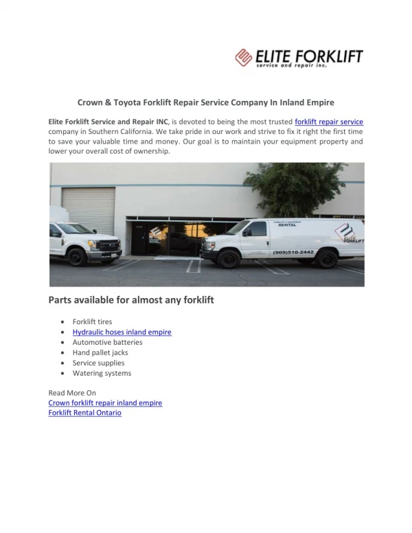
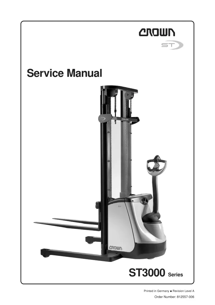
LUBRIFICATION AND ADJUSTMENT Lifting and Blocking INFORMATION WARNING To raise truck for additional jack clear- ance, fabricate a 1/2" board for load wheel or 3/4" board for drive wheel (8" x 12" with stop and bevel). Drive truck onto board and proceed with step 3. If truck can not be moved, use overhead lifting device for additional jack clearance. Always support a raised truck with wooden blocks or other appropriate equipment to relieve the jack. Move truck to a secure non traffic maintenance area with a level floor. ● Disconnect the battery and prevent the truck from being switched on again. ● No load on forks. ● Tools required Hydraulic Jack - Capacity 3620 kg. (8000 lbs.) Crown part number: 122599 Collapsed height minimum: 60 mm (2.25 in.) Raised height maximum: 400 mm (16 in.) ● Lower Forks Completely Jack Stand - capacity 4500 kg. (10,000 lbs.) Commercially available. ● Fabricated Board Lifting Straps - Capacity 900 kg (2000 lbs.) Commercially available. ● Barrel Hooks - Capacity 900 kg (2000 lbs.) Commercially available. ● Load Wheel Steer Wheel Hard Wood Block Raise Forks 70 to 150 mm from Floor Wheel Chock Load Wheel Both Outriggers MS01-3130-002 WARNING Place Jack Stand on Opposite Side of other Jack Truck stability decreases dramatically if load wheels are raised more than 13 mm (0.5 inch). Attach sling and overhead lifting device to all cross members of the mast to prevent truck from tipping over when raising the side of the truck. Set Jack Stand Height as Required Not to Exceed 300 mm MS01-3130-0003 ST3000 10/2004 • Printed in Germany MS-1.0-3130 M1.0-0000-00013 13
Thank you very much for your reading. Please Click Here. Then Get COMPLETE MANUAL. NO WAITING NOTE: If there is no response to click on the link above, please download the PDF document first and then click on it.
LUBRIFICATION AND ADJUSTMENT Outriggers Note that the outriggers are evenly distanced from the chassis: Dimension A= Dimension B INFORMATION Outrigger bolt torque: 380 Nm! M o l e d n I d i s e S r t a d e l d S T 3 0 0 0 9 6 5 m m - 1 2 7 0 m m S T 3 0 0 0 N 8 6 5 m m - 1 1 6 5 m m M01-GB Outrigger bolts Dimension B Dimension A Outrigger internal length MS01-3130-004 MS-1.0-3130 ST3000 10/2004 • Printed in Germany M1.0-0000-00014 14
LUBRIFICATION AND ADJUSTMENT Restoring the Truck to Service Recommended Lubricants and Oils When restoring the truck to service, proceed as follows: Lubricants Remove any addition corrosion protection applied (except for cold store protection)*. ● The following page lists typical lubricants which are also used by Crown in the factory. However, any lubricants with the same technical specifications can be used. Jack up the truck, remove the wooden blocks and lower the truck. ● Cold Store Trucks Charge the battery or install a charged battery. ● Special hydraulic oil, lubricant oils and grease for low temperature applications must be used for cold store trucks (see table on following page). All screws, wash- ers, nuts, pins, retaining rings etc. must be treated regu- larly with an anti-corrosion solution CROWN no. 805236- 004. Electrical connections and components must be carefully protected against corrosion. For more details refer to chapter 4. Connect the battery. ● Carry out the daily check. ● * Do not use high pressure cleaners and/or solvents on the truck. Do not use metal brushes. Do not wet- clean the electrical system and do not use flamma ble cleaning solutions. Maintenance intervals must be adapted to the conditions of use. They should be as frequent as possible to pre- vent excess wear. Truck Decommissioning When taking the truck out of service for more than 3 months, proceed as follows: Disconnect the battery. ● Decommission the battery in accordance with the manufacturer's instructions. ● Clean the truck*). Wipe off any grease in accord- ance with the maintenance manual. ● If the truck is to be stored in hostile ambient conditions (e.g. saline atmosphere) treat the surfaces of the truck with a suitable solution to prevent corrosion. ● Jack up the truck. Lower the chassis onto suit- able wooden blocks in order to clear the wheels from the ground (this prevents the wheels from flattening under constant pressure). ● Every 3 months connect the battery, carry out a daily check and test the truck functions. Then disconnect the battery again. ● ST3000 10/2004 • Printed in Germany MS-1.0-3130 M1.0-0000-00015 15