Download
1 / 15
150 likes | 387 Views
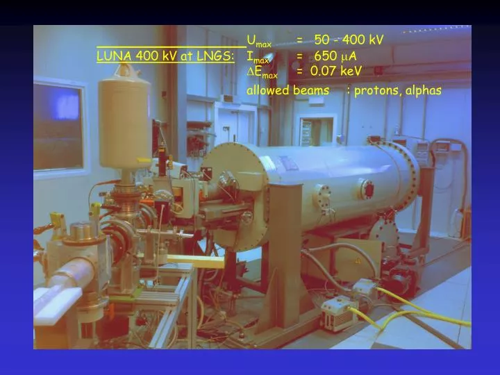
U max = 50 - 400 kV LUNA 400 kV at LNGS: I max = 650 A E max = 0.07 keV allowed beams : protons, alphas. LUNA II Foto. LUNA underground Laboratories. LUNA 50kV. LUNA 400kV. LUNA 2 site. BGO detector. 50. 14 N(p, ) 15 O Simulation. 2000 Channels 20000 seeds.

E N D
Umax = 50 - 400 kV LUNA 400 kV at LNGS: Imax = 650 A Emax = 0.07 keV allowed beams : protons, alphas LUNA II Foto
LUNA underground Laboratories LUNA 50kV LUNA 400kV LUNA 2 site
BGO detector 50 14N(p,)15O Simulation 2000 Channels 20000 seeds 30 10 6 Background Spectrum Measured Underground 10 10 4 0 2000 4000 6000 8000 E>5.5 MeV: 4.4 cts/MeV/day Energy / keV 10 2 4096 Channels 12.5 days 10 0 2000 4000 6000 8000 Energy / keV Near the Gamow peak: BGO detector4 summing chrystal
target calorimeter beam
D(p,g) D(p,)3He LUNA data Ecm= 10 keV
Ecm= 6 keV Viviani et al. PRC61 (2000) D(p,)3He below the Gamow peak = 0.01 pbarn
P + d all D(p,)3He
Beam calorimeter gas to pumps heater cooling system T = const. beam hot side cold side gas from trap heater (transistor, resistor, ..) provides W T is kept constant by a feedback system without beam: W0 = R-1 (Th-Tc) + Wloss (Wloss = const. at fixed T) with beam: Wbeam+ W = R-1 (Th-Tc) + Wloss Wbeam = W0 –W Ibeam = Wbeam/Ebeam
windowless gas target target chamber collimators beam p=0.3 mbar I I I zeolite trap gas cleaner I turbo pump roots blowers I I
Fig 1 nuovo acceleratore da 400 kV Fig 2 mappa laboratori sotterranei Fig 3 rivelatore BGO usato per la p+d Fig 4 rivelatore BGO + stadi pompaggio gas target Fig 5 in primo piano stadio pompaggio gas target, in alto rivelatore BGO (il fascio di protoni “entra” dal basso Fig 6 vista laterale di stadio pompaggio + BGO Fig 7 uno spettro dei fotoni da 5.5 MeV Fig 8 come sopra Fig 9 le misure esistenti Fig 10 dettagli sul calorimetro per la misura della corrente del fascio (da una misura di potenze termica depositata, nota l’energia Fig 11 shema gas target con ricircolo deuterio