Download
1 / 100
1.09k likes | 1.56k Views
18. GASOLINE ENGINE OPERATION, PARTS, AND SPECIFICATIONS. Objectives. The student should be able to: Prepare for Engine Repair (A1) ASE certification test content area “A” (General Engine Diagnosis). Explain how a four-stroke cycle gasoline engine operates.

E N D
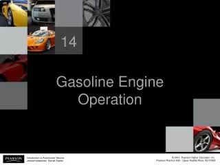
18 GASOLINE ENGINE OPERATION, PARTS, AND SPECIFICATIONS
Objectives • The student should be able to: • Prepare for Engine Repair (A1) ASE certification test content area “A” (General Engine Diagnosis). • Explain how a four-stroke cycle gasoline engine operates. • List the various characteristics by which vehicle engines are classified.
Objectives • The student should be able to: • Discuss how a compression ratio is calculated. • Explain how engine size is determined. • Describe how displacement is affected by the bore and stroke of the engine.
Purpose and Function • Convert heat energy of burning fuel into mechanical energy • Mechanical energy is used to perform the following: • Propel the vehicle
Purpose and Function • Mechanical energy is used to perform the following: • Power the air-conditioning system and power steering • Produce electrical power for use throughout the vehicle
Energy and Power • Engines use energy to produce power • Combustion: fuel is burned at a controlled rate to convert chemical energy to heat energy
Energy and Power • Combustion occurs within the power chamber in an internal combustion engine • Engines in automobiles are internal combustion heat engines
Energy and Power • NOTE: An external combustion engine burns fuel outside of the engine itself, such as a steam engine.
Engine Construction Overview • Block • Solid frame from which all automotive and truck engines are constructed • Constructed of cast iron or aluminum
Engine Construction Overview • Rotating Assembly • Constructed of pistons, connecting rods and a crankshaft
Figure 18-1 The rotating assembly for a V-8 engine that has eight pistons and connecting rods and one crankshaft.
? Engine Construction Overview • Cylinder Heads • Seal top of cylinders in the engine block • Contain both intake valves and exhaust valves • Constructed of cast iron or aluminum
Figure 18-2 A cylinder head with four valves per cylinder, two intake valves (larger) and two exhaust valves (smaller).
Engine Parts and Systems • Intake and Exhaust Manifolds • Air and fuel enter and exit the engine through manifolds • Intake manifolds are constructed of nylon-reinforced plastic or aluminum
Engine Parts and Systems • Intake and Exhaust Manifolds • Exhaust manifolds must withstand hot gases and are constructed of cast iron or steel tubing
Engine Parts and Systems • Cooling System • Controls engine temperature • Vehicles are cooled by circulating antifreeze coolant
Engine Parts and Systems • Cooling System • Coolant picks up heat and releases it through radiator
Figure 18-3 The coolant temperature is controlled by the thermostat, which opens and allows coolant to flow to the radiator when the temperature reaches the rating temperature of the thermostat.
Engine Parts and Systems • Lubrication System • Oil is pumped from oil pan through oil filter, then into oil galleries to lubricate engine parts
Figure 18-4 A typical lubrication system, showing the oil pan, oil pump, oil filter, and oil passages.
Engine Parts and Systems • Fuel System and Ignition System • Fuel system includes the following components: • Fuel tank – stores fuel and contains most fuel pumps
Engine Parts and Systems • Fuel System and Ignition System • Fuel system includes the following components: • Fuel filter and lines - transfer fuel for the fuel tank to the engine
Engine Parts and Systems • Fuel System and Ignition System • Fuel system includes the following components: • Fuel injectors - spray fuel into intake manifold or directly into the cylinder
Engine Parts and Systems • Fuel System and Ignition System • Ignition system includes the following components: • Spark plugs - provide an air gap inside the cylinder where a spark occurs to start combustion
Engine Parts and Systems • Fuel System and Ignition System • Ignition system includes the following components: • Sensor(s) - includes crankshaft position (CKP) and camshaft position (CMP)
Engine Parts and Systems • Fuel System and Ignition System • Ignition system includes the following components: • Ignition coils - increase battery voltage to 5,000 to 40,000 volts
Engine Parts and Systems • Fuel System and Ignition System • Ignition system includes the following components: • Ignition control module (ICM) - controls when the spark plug fires
Engine Parts and Systems • Fuel System and Ignition System • Ignition system includes the following components: • Associated wiring - electrically connects the battery, ICM, coil, and spark plugs
Four-Stroke Cycle Operation • Principles • First four-stroke cycle engine developed by Nickolaus Otto in 1876 • The process begins with the starter motor rotating the engine until combustion takes place
Four-Stroke Cycle Operation • Principles • The cycle is repeated for each cylinder of the engine • Piston is attached to crankshaft with a connecting rod allowing the piston to move up and down
Figure 18-5 The downward movement of the piston draws the air-fuel mixture into the cylinder through the intake valve on the intake stroke. On the compression stroke, the mixture is compressed by the upward movement of the piston with both valves closed. Ignition occurs at the beginning of the power stroke, and combustion drives the piston downward to produce power. On the exhaust stroke, the upward-moving piston forces the burned gases out the open exhaust valve.
Figure 18-6 Cutaway of an engine showing the cylinder, piston, connecting rod, and crankshaft.
Four-Stroke Cycle Operation • Operation • Engine cycles are identified by the number of piston strokes required to complete the cycle
Four-Stroke Cycle Operation • Operation • Piston stroke: one-way piston movement • Most engines use a four-stroke cycle
Four-Stroke Cycle Operation • Operation • Most engines use a four-stroke cycle • Intake stroke • Compression stroke
Four-Stroke Cycle Operation • Operation • Most engines use a four-stroke cycle • Power stroke • Exhaust stroke
Four-Stroke Cycle Operation • The 720-Degree Cycle • In each cycle, the engine crankshaft makes two complete revolutions (or 720 degrees)
Four-Stroke Cycle Operation • The 720-Degree Cycle • To find the angle between cylinders of an engine, divide the number of cylinders into 720 degrees
Engine Classification and Construction • Engines are classified by several characteristics including: • Number of strokes • Cylinder arrangement
Engine Classification and Construction • Engines are classified by several characteristics including: • Longitudinal and transverse mounting • Valve and camshaft number and location
Engine Classification and Construction • Engines are classified by several characteristics including: • Type of fuel • Cooling method • Type of induction pressure
? Engine Classification and Construction • NOTE: Although it might be possible to mount an engine in different vehicles both longitudinally and transversely, the engine component parts may not be interchangeable. Differences can include different engine blocks and crankshafts, as well as different water pumps.
Figure 18-8 A horizontally opposed engine design helps to lower the vehicle’s center of gravity.