Download
1 / 13
140 likes | 290 Views
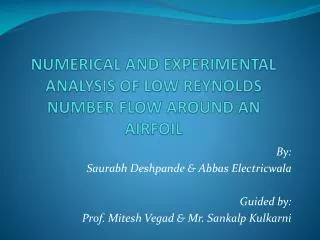
TC I.3: 3-Element high-lift airfoil Coordinated by DLR. Axel Probst , Silvia Reuß , Dieter Schwamborn Go4Hybrid Kick-Off meeting, Berlin, 10.10.2013. Introduction.

E N D
> Vortrag > Autor • Dokumentname > Datum TC I.3: 3-Element high-lift airfoilCoordinated by DLR Axel Probst, Silvia Reuß, Dieter Schwamborn Go4Hybrid Kick-Off meeting, Berlin, 10.10.2013
> Vortrag > Autor • Dokumentname > Datum Introduction • DLR-F15 3-element airfoil investigated in the DLR project LEISA (Low noise exposing integrated design for start and approach, 2005-2008) • Measurements in the low-speed wind-tunnel Braunschweig (NWB) with a model with chord length c = 0.6m, span = 2.8m, and thus AR = 4.66. • complexinteractionsoflocalseparations (bothgeometry- andpressure-induced) atconsidered AOA = 6° • used in ATAAC projectasApplicationChallange AC01 • large effortspent on preliminary RANS computationsto find suitedsettings (angle ofattackcorrection, transitionlocations, …) • however, suitablityasvalidationcase was still doubted… • depending on hybrid modellingstrategy, greyareasmayoccur in attached, mildlyandstronglyseparatedregions • usefultotestboth non-zonal andembeddedmitigationapproaches
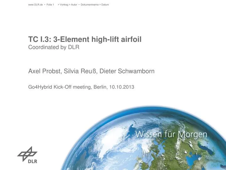
> Vortrag > Autor • Dokumentname > Datum Geometric description /Description of available reference data Geometry: • asciifilewithpointdataof airfoil geometry (still on ATAAC website) • farfieldextentof 100 chords (asgiven in mandatorygridshownlater) Reference data: • measuredmeansurfacepressurecp in different spanwisesections • measured total pressureprofiles in wake (not used in ATAAC) • measuredacoustic data from microphone wall arrays from 1kHz to 0.5MHz • “consolidated” SST-RANS results from DLR and NTS for mandatory grid • Note: due to experience from ATAAC, comparison CFD vs. experiment (i.e. validation) is not primary goal. Instead, focus is set on model-to-model and code-to-code comparisons.
> Vortrag > Autor • Dokumentname > Datum Design and assessment parameters /Description of errors and known uncertainties Assessment parameters: • cp distributions can be compared with measurements (with all care!) • for comparisons of simulations, consider the following parameters: • mean surface distributions of cp and cf • lift/drag coefficients, separation/reattachment locations • wall-normal mean velocity and Reynolds-stress profiles along the airfoil (locations to be defined) • cp,RMSon whole or in points along surface (locations to be defined) • PSD spectra of velocity and/or pressure at various points on the surface and in the field (locations to be defined) Uncertainties: • due to large 3D / wind-tunnel effectsanduncertaintransitionlocations in theexperiment, thiscaseis not proposedfor experimental validation
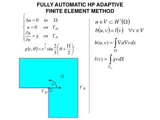
Physical phenomena and modelling challenges /Relevant modelling techniques stable/unstablefree shear layer • non-zonal mitigation LES → RANS RANS → LES stable attached BL • embedded RANS? unstablegeometry-induced separation • non-zonal mitigation ? • embedded LES? stable pressure-induced separation • embedded LES
> Vortrag > Autor • Dokumentname > Datum Sample resultsoffull SST.1994 - IDDES
Snapshots of Vorticity Magnitude (DLR) gap in resolved structures ratherstableshearlayers
Skin friction coefficient (DLR) “dent” in cf on main wing (similar findings by NTS) Note: displayed is |c_f| * sign(c_f,x) cf“kink” on flap, not seen in RANS(similar findings by NTS)
Possibleembeddedconfigurations synthet. turbulence RANS-mode synthet. turbulence RANS-mode LES-mode LES-mode LES-mode synthet. turbulence synthet. turbulence LES-mode Pictures providedby T. Knopp LES-mode synthet. turbulence
> Vortrag > Autor • Dokumentname > Datum Flow and boundary conditions /Grids Boundary conditions: • Mean flow: Re = 2.094 Mio., Ma = 0.15, α = 6° • Turbulence: laminar freestream, e.g. (νt/ν)∞=0.1, Tu∞ = (2/3 k∞)1/2/U∞ = 1∙10-3 (however, this should not affect most models!) • fully turbulent BLs on airfoil surface • maybeunphysical, but preferablefor code-to-code comparisons Mandatorygrid (suggested): • structuredgridprovidedby NTS for IDDES • span size Lz= 0.08 c with 100 grid cells, ~ 27 mio. cells total • farfield distance at 100 chords • Note: contains (some) non-orthogonal grid lines
> Vortrag > Autor • Dokumentname > Datum Computational guidelines • spatialdomainextentanddiscretizationasgiven in mandatorygrid • Temporal settings: • suggested time step: Δt = 2∙10-4 c/U∞ • initial transient phase (starting from RANS solution): > 4CTU • averaging time: > 10CTU • 2nd-order discretizationofturbulenceequationsrequired? • large impact on RANS resultseven on mandatory (IDDES) grid • foundbyboth DLR and NTS
> Vortrag > Autor • Dokumentname > Datum Mandatory and optional results Mandatoryresults: • meansurfacevalues (cp, cf) andfieldprofiles (velocity, Reynolds stresses) • distinctionbetweenmodelledandresolvedturbulence • cp,RMSin points along surface (locations to be defined) • visualizations of turbulent structures via Q-criterion Optional results: • PSD spectra of velocity and/or pressure (locations to be defined) • cp,RMSdistribution on surface • spanwise two-point pressure correlations • …?
> Vortrag > Autor • Dokumentname > Datum References [1] Wild, J., Pott-Pollenske, M. (2006) An Integrated Design Approach for low Noise exposing high-lift devices. AIAA paper 2006-2843 [2] Reuß, S., Knopp, T., Schwamborn, D. (2012) Hybrid RANS/LES simulations of a three-element airfoil. NNFMMD, Vol. 117: Progress in Hybrid RANS-LES Modelling. [3] Deck, S., & Laraufie, R. (2013). Numerical investigation of the flow dynamics past a three-element aerofoil. Journal of Fluid Mechanics, 732, 401–444.