Download
1 / 13
130 likes | 364 Views
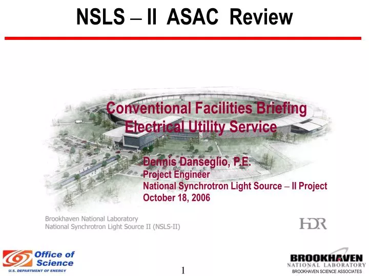
NSLS – II ASAC Review. Conventional Facilities Briefing Electrical Utility Service Dennis Danseglio, P.E. Project Engineer National Synchrotron Light Source – II Project October 18, 2006. Electrical Utility Service .

E N D
NSLS – II ASAC Review Conventional Facilities Briefing Electrical Utility Service Dennis Danseglio, P.E. Project Engineer National Synchrotron Light Source – II Project October 18, 2006
Electrical Utility Service • BNL site has sufficient power available so there is adequate capacity to add all loads associated with NSLS II. • Electrical power to the NSLS II is available from existing 69 kV to 13.8 kV substation 603 located near the intersection of Cornell Avenue and North Sixth street. • Estimated peak load at full build out is 14 MW • Estimated peak load for CWF expansion is 5 MW provided by a separate existing feeder. This takes into consideration 3600 tons of Chilled Water for NSLS II and 1200 ton for BNL site.
BNL Site - One Line Diagram Feed to NSLS II
Electrical Utility Service (cont’d) • Upgrade to existing substation 603 will include: • Modification to the existing 69 kV support structure. • Relocation of two (2) 69 kV Potential Transformers. • Minor Expansion of Building 603 by 350 square feet. • Installation of firewall between existing transformer # 3 and new transformer. • 69 kV SF6 Breaker. • 20.0/26.7/29.9 MVA transformer. • 2000 A 15 kV overhead busway. • 15 kV metal clad switchgear. • 15 kV tie breakers.
Building 603 Substation New Work
Electrical Utility Service (cont’d) • NSLS II 13.8 kV Power Distribution • 600 A feeder consisting of 2 sets of 3-1/C 750 kcmil , 15 kV , 133%EPR copper conductors • Conductors will be routed through an existing manhole and ductbank system from the new switchgear in building 603 to a new 6-way , 600 A 15 kV SF6 low profile pad mounted switchgear located on the NSLS II project site. • A cable vault will be provided under the switchgear and a 12 way 5” concrete encased ductbank will tie the vault to existing manhole MH-E5.
Electrical Utility Service (cont’d) • NSLS II Site Distribution • An 8-way 5” concrete encased ductbank will be routed from existing manhole MH-E5 to a new manhole in the infield of the Ring Building via a utility tunnel. • A 6-way 5” ductbank will then be routed around the infield interconnecting all the substations at each of the service buildings. • Two 600 A feeders will then be routed from the SF6 padmount switchgear into the Ring Building infield and around the infield providing a redundant on site primary radial distribution system.
Electrical Utility Service (cont’d) • One substation will be located at each of the service buildings 1-4. • Two substations will be located at the service building 5 associated with the Central Lab office and the LINAC and RF buildings. • Each substation will consist of: • 15 kV outdoor non-walk-in metal enclosed switchgear. This will include two switches in parallel feeding the fused load switch. • Fused load interrupter switch. • 13.8 kV -480/277 V oil filled substation type transformer. • Secondary air terminal section with 480V Breakers.
Electrical Utility Service (cont’d) • The 13.8 kV electrical distribution cable/ductbank infrastructure from the SF6 pad-mounted switch to the inside diameter of the Ring Building has been designed for a redundant 600 Amp feeder. • Presently the base design includes a single feeder from Bldg. 603 substation to the NSLS II project site utilizing an existing ductbank. • Estimates indicate that the cost of installing a redundant 13.8 kV 600 amp feeder to the SF6 switch in a new ductbank and installing a redundant substation transformer at each of the service buildings will cost approximately $2.1 million. • This will provide complete redundancy from Bldg. 603 substation to the electrical equipment located in each service building. This will be evaluated as we approach CD-1 and review all the costs associated with the NSLS II project.
Electrical Utility Service (cont’d) • Chilled Water Plant Substation Expansion • A new fused load interrupter switch will be added to the existing Switchgear 600A lineup. • The existing two transformer substation yard will be expanded to include a third 7500 kVA 13.8 kV -4160/2400 volt transformer. • A 5kV feeder will be routed in a ductbank to 5kV metal-clad switchgear within the Chiller Building expansion. • A bus tie breaker will be installed in the new switchgear to electrically connect the existing 4160 volt bus to the new bus. This will ensure reliable power to the CWF expansion.
CWF - ONE LINE DIAGRAM New Work