Download
1 / 29
340 likes | 548 Views
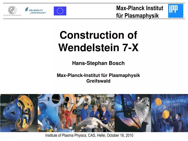
Max-Planck Institut für Plasmaphysik. Construction of Wendelstein 7-X Hans-Stephan Bosch Max-Planck-Institut für Plasmaphysik Greifswald. Institute of Plasma Physics , CAS, Hefei, October 18, 2010. Stellarator Wendelstein 7-X. Optimisation criteria small neo- classical transport

E N D
Max-Planck Institut für Plasmaphysik Constructionof Wendelstein 7-X Hans-Stephan Bosch Max-Planck-Institut für Plasmaphysik Greifswald Institute of Plasma Physics, CAS, Hefei, October 18, 2010
Stellarator Wendelstein 7-X Optimisationcriteria • small neo-classicaltransport • goodconfinementof fast particles • minimisedbootstrapcurrent • good MHD stability • good finite b-equilibria • feasible modular coils Modular stellarator, Superconductingcoils Fullyoptimizednumerically
W7-X, plasma Pentagon-shaped 5 identicalmodules, eachmadeof 2 flip-symmetric half-modules
W7-X, divertor • 10 separate divertor units • 2 in each of the 5 modules • designed for a maximum heat load of 10 MW/m2
W7-X, in-vesselcomponents • Two step approach requires intermediate components: • Inertial cooled divertor (TDU) for first operation phase • Actively cooled high-heat-flux (HHF)divertor for steady state phase
W7-X, in-vesselcomponents, status • Target plates • prototypes finished • manufacturing started • heat shields • structure in manufacturing • The graphite tiles are also • in manufacture • wall panels • all 320 panels have • been delivered by MAN • DWE (Germany)
W7-X, plasmavessel • volume 110 m3 • surface 200 m2 • mass 33 t • vacuum < 10-8mbar • bakingupto 150o C • tolerances < 2 mm
W7-X, plasma and plasma vessel Multi-Layer Insulation • 20 layers of crinkled Kapton foil • glass mats in between Thermal shield • glass fibre panels, Al coated • Cu braids for connection to water cooling • 20 welded rings per half-module
W7-X, magnet system BNN, G / Ansaldo, I / Tesla, GB • magneticfield in plasma 2.5 T (< 3T) • magneticfieldenergie 600 MJ • NbTisuperconductor (>3.4 K) • 50 non-planarcoils (5 types) • 20 planarcoils (2 types)
NbTisuperconductorforW7-X 0,58 m fibre NbTiwith Cu cabling 243 singlefibres (3 x 3 x 3 x 3 x 3) Cable-in-Conduit (Coextrusion) Inup to17.6 kA
Wendelstein 7-X, coilfabrication I Coilwinding (ABB, Augsburg) Temperingofcastcasing /half shell (Österby, Sweden)
Wendelstein 7-X, coilfabricationII Assemblyofwinding pack in casing Overviewof production hall (BNN, Zeitz)
Wendelstein 7-X, Cryogenictestingofcoils • CEA Saclay, France: • Tests at 5K • Thermal properties • Cold leak tightness • Helium flow rates • Electrical insulation • Superconductivity
Wendelstein 7-X, Paschen testingofcoils • criticalscenario: airinfluxintocryovacuumcausespressureincreaseand • quenchof a coil • High voltage @ highpressure Paschen dischargepossible • Therefore all coilsaretestedunder Paschen conditions (between • 0.001 and 100 mbar) with 6 kV • Thishasproventobe a valuablemeasuretoverifyinsulationquality.
W7-X, supportstructure Ensa, Spain • welded ring in 10 half-modules • mass: 71 t • Support of all coils, highprecision • extensive inter-coilsupport • structuretopreventmovementof • coils
W7-X, outervesselandports DWE, Germany ROMABAU Romabau, Switzerland • volume 525 m3 • surface 480 m2 • mass 170 t • vacuum < 10-5 mbar • number of ports 254
W7-X, outervesselandports • All 5 modulesdelivered • Installation of Thermal Insulationongoing
W7-X, pre-assembly • The coil support structure • is positioned in front of the • 7-coil pack • Coils are bolted to the • central support ring Coils are threaded across the plasma vessel Thermal insulation is completed
W7-X, pre-assembly II • The flip-symmetric half-modules are aligned • The step-flange is bolted and the vessel half-modules are welded • Thermal insulation, Inter-coil structure are completed
W7-X, assembly Module 5, February 2009
Assemblyschedule • Assembly of the five modules is running in parallel • All 5 modules are in the works at present • Major “new” work packages: • module connection • diagnostics • in-vessel assembly • The assembly schedule still contains half a year buffer times • Assembly will be finished in summer 2014 • periphery installations
Operationsplanning • stepwiseapproach • 1st operationphasewith 10s @ 8MW, inertiallycooleddivertor • andonly partial coolingof in-vesselcomponents • shut-down (15 months) forcompletionandhardening • 2nd operationphasetoapproach 30min @ 10MW