Download

1 / 28
500 likes | 1.36k Views
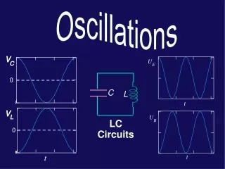
U. E. t. U. B. t. V. C. 0. C. L. V. L. LC Circuits. 0. t. A little review Oscillating voltage and current Qualitative descriptions: LC circuits (ideal inductor) LC circuits ( L with finite R ) Quantitative descriptions: LC circuits (ideal inductor)

E N D
U E t U B t V C 0 C L V L LC Circuits 0 t
A little review Oscillating voltage and current Qualitative descriptions: LC circuits (ideal inductor) LC circuits (L with finite R) Quantitative descriptions: LC circuits (ideal inductor) Frequency of oscillations Energy conservation? Today... Text Reference: Chapter 31.1, 31.3, and 31.5 Example: 31.4
I(t) C I(t) Voltage determined by derivative of current and inductance L Review of Voltage DropsAcross Circuit Elements Voltage determined by integral of current and capacitance
Why and how do oscillations occur in circuits containing capacitors and inductors? naturally occurring, not driven for now stored energy capacitive <-> inductive Where are we going? • Oscillating circuits • radio, TV, cell phone, ultrasound, clocks, computers, GPS What’s Next?
eosinwt I(t) Oscillating circuits have both AC voltage and current. Simple for resistors, but... Þ ~ ~ eosinwt R Oscillating Current and Voltage Q. What does mean?? A. It is an A.C. voltage source. Output voltage appears at the terminals and is sinusoidal in time with an angular frequency w.
Energy in the Electric and Magnetic Fields Energy stored in a capacitor ... E +++ +++ - - - - - - … energy density ... B Energy stored in an inductor …. … energy density ...
Consider from point of view of energy! In the RC circuit, any current developed will cause energy to be dissipated in the resistor. In the LC circuit, there is NO mechanism for energy dissipation; energy can be stored both in the capacitor and the inductor! ++++ - - - - ++++ - - - - C C R L LC Circuits • Consider the RC and LC series circuits shown: • Suppose that the circuits are formed at t=0 with the capacitor charged to value Q. There is a qualitative difference in the time development of the currents produced in these two cases. Why??
I I Q +++ Q C L +++ - - - C R - - - LC: current oscillates RC: current decays exponentially 0 I 0 -I 0 0 t t RC/LC Circuits
+ + C C L L - - - - C C L L + + LC Oscillations(qualitative) Þ ß Ý Ü
C VC V=0 VL L VC+VL= 0 VC= -VL Alternate way to draw:
Q 0 V C 0 I 0 V L 0 t t LC Oscillations(qualitative) These voltages are opposite, since the cap and ind are traversed in “opposite” directions dI dt 0
Att=0, the capacitor in the LCcircuit shown has a total charge Q0. At t = t1, the capacitor is uncharged. What is the value of Vab=Vb-Va, the voltage across the inductor at timet1? t=t t=0 1 a + + = = Q 0 L L Q Q 0 - - C C 1A b (c)Vab> 0 (b)Vab = 0 (a)Vab < 0 • What is the relation between UL1, the energy stored in the inductor at t=t1, and UC1, the energy stored in the capacitor at t=t1? 1B (c) UL1 > UC1 (b)UL1 = UC1 (a)UL1 < UC1 Lecture 18, Act 1
Att=0, the capacitor in the LC circuit shown has a total charge Q0. At t = t1, the capacitor is uncharged. What is the value of Vab=Vb-Va, the voltage across the inductor at timet1? t=t t=0 1 a + + = = Q 0 L L Q Q 0 - - C C 1A b (c)Vab> 0 (b)Vab = 0 (a)Vab < 0 Lecture 18, Act 1 • Vab is the voltage across the inductor, but it is also (minus) the voltage across the capacitor! • Since the charge on the capacitor is zero, the voltage across the capacitor is zero!
Att=0, the capacitor in the LC circuit shown has a total charge Q0. At t = t1, the capacitor is uncharged. t=t t=0 1 a + + L L = = Q 0 Q Q - 0 - C C 1B b • At t=t1, the charge on the capacitor is zero. • At t=t1, the current is a maximum. (c) UL1 > UC1 (b)UL1 = UC1 (a)UL1 < UC1 Lecture 18, Act 1 • What is the relation between UL1, the energy stored in the inductor at t=t1, and UC1,the energy stored in the capacitor at t=t1?
If L has finite R, then energy will be dissipated in R. the oscillations will become damped. Q Q 0 0 t t R¹ 0 R = 0 LC Oscillations(L with finite R)
where f,Q0determined from initial conditions I + + Q C L - - remember: LC Oscillations(quantitative, but only for R=0) • What is the oscillation frequency ω0? • Begin with the looprule: • Guess solution:(just harmonic oscillator!) • Procedure: differentiate above form for Q and substitute into loop equation to findw0. • Note: Dimensional analysis
General solution: + + C L - - • Differentiate: • Substitute into loop eqn: Þ Therefore, which we could have determined from the mass on a spring result: LC Oscillations(quantitative)
At t=0 the capacitor has charge Q0; the resulting oscillations have frequency w0. The maximum current in the circuit during these oscillations has value I0. What is the relation between w0and w2, the frequency of oscillations when the initial charge =2Q0? 2A (c) w2 = 2w0 (b)w2 = w0 (a) w2 = 1/2 w0 • What is the relation between I0and I2,the maximum current in the circuit when the initial charge =2Q0? 2B (c)I2 = 4I0 (b)I2 = 2I0 (a)I2 = I0 Lecture 18, Act 2
At t=0 the capacitor has charge Q0; the resultingoscillations have frequency w0. The maximum current in the circuit during these oscillations has value I0. What is the relation betweenw0and w2, the frequency of oscillations when the initial charge = 2Q0? 2A (c) w2 = 2w0 (b)w2 = w0 (a)w2 = 1/2 w0 Lecture 18, Act 2 • Q0 determines the amplitude of the oscillations (initial condition) • The frequency of the oscillations is determined by the circuit parameters(L, C),just as the frequency of oscillations of a mass on a spring was determined by the physical parameters(k, m)!
At t=0 the capacitor has charge Q0; the resultingoscillations have frequency w0. The maximum current in the circuit during these oscillations has value I0. What is the relation betweenI0 and I2, the maximum current in the circuit when the initial charge = 2Q0? 2B (c)I2 = 4I0 (b)I2 = 2I0 (a)I2 = I0 Lecture 18, Act 2 • The initial charge determines the total energy in the circuit: • U0 = Q02/2C • The maximum current occurs whenQ=0! • At this time, all the energy is in the inductor:U = 1/2 LIo2 • Therefore, doubling the initial charge quadruples the total • energy. • To quadruple the total energy, the max current must double!
The other unknowns(Q0,f)are found from the initial conditions. E.g., in our original example we assumed initial values for the charge(Qi)and current(0). For these values: Q0 = Qi,f = 0. • Oscillation frequency has been found from the loop equation. LC OscillationsEnergy Check • Question: Does this solution conserve energy?
Energy in Capacitor Energy in Inductor 0 t Þ U B Therefore, 0 t Energy Check U E
Att=0the current flowing through the circuit is 1/2 of its maximum value. Which of the following plots best representsUB,the energy stored in the inductor as a function of time? I + + Q C L - - 3A (c) f = 60° (b) f = 45° (a) f = 30° 3B (c) (b) (a) • Which of the following is a possible value for the phasef,when the charge on the capacitor is described by:Q(t) = Q0cos(wt + f) UB UB UB 0 0 0 0 0 0 time time time Lecture 18, Act 3
Att=0 the current flowing through the circuit is 1/2of its maximum value. Which of the following plots best representsUB, the energy stored in the inductor as a function of time? I + + Q C L - - 3A (c) (b) (a) UB UB UB 0 0 0 0 0 0 time time time Lecture 18, Act 3 • The key here is to realize that the energy stored in the inductor is proportional to the CURRENT SQUARED. • Therefore, if the current at t=0 is 1/2 its maximum value, the energy stored in the inductor will be 1/4 of its maximum value!!
Att=0the current flowing through the circuit is 1/2 of its maximum value. Which of the following is a possible value for the phasef, when the charge on the capacitor is described by:Q(t) = Q0cos(wt + f) I + + Q C L - - 3B (c) f = 60° (b) f = 45° (a) f = 30° • We are given a form for the charge on the capacitor as a function of time, but we need to know the current as a function of time. • At t = 0, the current is given by: Þ • Therefore, the phase angle must be given by: Lecture 18, Act 3
Quantitative description Frequency of oscillations Energy conservation V C 0 V L 0 • Oscillating voltage and current • Qualitative description Summary Text Reference: Chapter 31.1, 31.3, and 31.5
Reading assignment: Ch. 31.2 through 31.5, 31.7 Next Time... • AC power! • AC circuits ! Examples: 31.1-3, 31.9
Appendix: LCR DampingFor your interest, we do not derive here, but only illustrate the following behavior Q + + C L - - 0 t In an LRC circuit, w depends also on R ! Q 0 t