Download
1 / 17
170 likes | 344 Views
ECE543 Intro to Digital Systems. Lecture 36 Propagation Delay in Counter Designs II. 04/26/2013. Announcement. Postpone homework 9 to 4/29 (Monday) Homework #10 7-45, 9-1, 9-3, 9-5, 9-8, 9-16 Due May 3 rd (Friday) Final Exam May 13 (Monday), 6-8pm Kingsbury N343 Overview classes

E N D
ECE543Intro to Digital Systems Lecture 36 Propagation Delay in Counter Designs II 04/26/2013
Announcement • Postpone homework 9 to 4/29 (Monday) • Homework #10 • 7-45, 9-1, 9-3, 9-5, 9-8, 9-16 • Due May 3rd (Friday) • Final Exam • May 13 (Monday), 6-8pm • Kingsbury N343 • Overview classes • May 3rd and May 6th ECE543-Intro to Digital Systems 2
Outline • Overview • Propagation delay • Timing diagram for counter design • Synchronous counter • Asynchronous counter • Clock period and frequency • Computational block design ECE543-Intro to Digital Systems 3
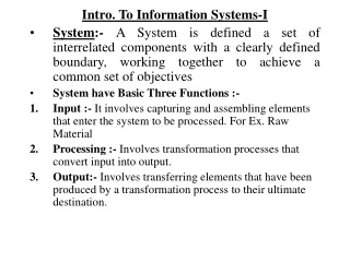
Flip-Flop Timing Considerations - Parameters • Important timing parameters: • Setup and hold times • Propagation delay • Maximum clocking frequency ECE543-Intro to Digital Systems 4
MOD-16 TCLK CLK 1 0 A FF tpd 1 0 B FF tpd 1 0 TCLK, min ANDtpd TCLK >= AND tpd + FF tpd AB 1 0 FF tpd C
MOD-6 Counter • State transition diagram for the MOD-6 counter • Circle state; arrow state change • Clear a MOD-8 counter when a count of six (110) occurs ECE543-Intro to Digital Systems 6
MOD-6 Counter • B output contains a spike or glitch • Caused by the momentary occurrence of the 110 state MOD-6 counter produced by clearing a MOD-8counter when a count of six (110) occurs. ECE543-Intro to Digital Systems 7
4 1 2 3 5 6 7 CLK 1 0 A FF tpd 1 0 FF tpd B FF tpd 1 0 C 1 0 BC NANDtpd ECE543-Intro to Digital Systems 8
4 1 2 3 5 6 7 CLK 1 0 A FF tpd 1 0 FF tpd B FF tpd 1 0 CLRtpd C 1 0 BC NANDtpd ECE543-Intro to Digital Systems 9
4 1 2 3 5 6 7 CLK 1 0 A FF tpd 1 0 FF tpd B FF tpd 1 0 CLRtpd C 1 0 BC NANDtpd ECE543-Intro to Digital Systems 10 NANDtpd
MOD-6 Counter • B output contains a spike or glitch • Caused by the momentary occurrence of the 110 state MOD-6 counter produced by clearing a MOD-8counter when a count of six (110) occurs. ECE543-Intro to Digital Systems 11
CLK 1 0 A FF tpd 1 0 B FF tpd 1 0 TCLK’ C 1 0 BC ECE543-Intro to Digital Systems 12
Asynchronous (Ripple) Counter • Diagram • Waveform MSB LSB An asynchronous counter—state is notchanged in exact synchronism with the clock. ECE543-Intro to Digital Systems 13
Propagation Delay in Ripple Counters 50ns 50ns ECE543-Intro to Digital Systems 14
Homework 7-5 • Four-bit ripple counter with frequency f=20MHz (i.e. T=50ns), tpd=20ns= CLK 1 A 1 B C 1 1 D ECE543-Intro to Digital Systems 15
Homework 7-5 • Four-bit ripple counter with frequency f=20MHz (i.e. T=50ns), tpd=20ns. CLK 1 1 1 0 1 0 1 1 0 1 A 0 1 0 1 1 1 0 1 1 0 B 1 1 0 0 1 0 1 1 1 1 C 1 1 1 1 1 0 0 0 1 1 D ECE543-Intro to Digital Systems 16
Propagation Delay • Synchronous counter • Critical Path = FF tpd + sum of Logic gate tpds • The fastest frequency = 1/ Critical Path • Asynchronous (Ripple) counter • Critical Path = X * FF tpd(X, # of FFs used) • The fastest frequency = 1/ Critical Path ECE543-Intro to Digital Systems 17