Download

1 / 35
360 likes | 541 Views
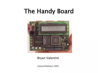
Handy Board. Why the Handy Board. Designed to be the controller of small, mobil robots Has many features that make it ideal for robotics projects Integrated motor drivers 32K bytes of memory LCD screen Integrated battery pack Interactive C Small size

E N D
Why the Handy Board • Designed to be the controller of small, mobil robots • Has many features that make it ideal for robotics projects • Integrated motor drivers • 32K bytes of memory • LCD screen • Integrated battery pack • Interactive C • Small size • Sensor connectors for digital and analog sensors
Handy Board Specifications • Motorola 6811 microprocessor with system clock at 2 MHz. • 32K of battery-backed CMOS static RAM. • Two L293D chips capable of driving four DC motors. • 16 x 2 character LCD screen. • Two user programmable buttons, one knob and one piezo beeper. • Powered header inputs for 7 analog sensors and 9 digital sensors.
Handy Board Specifications • Internal 9.6v nicad battery with built in recharging circuit. • Hardware 38 kHz oscillator and drive transistor for IR output and on-board 38 kHz IR receiver. • 8-pin powered connector to 6811 SPI circuit. • Expansion bus with chip selects. • 4.25 x 3.15 inches.
Expansion Board Specifications • 10 additional analog sensor inputs; • 4 inputs for active LEGO sensors (reflectance sensor and shaft encoder). • 9 digital outputs. • 6 servo motor control signals with power supply from the Handy Board's internal battery. • optional external power for servo motors.
Expansion Board Specifications • connector mount for Polaroid 6500 ultrasonic ranging system. • pass-through connector for the Handy Board's LCD screen.
Charging • Adapter plugged directly into board. trickle-charge. (12-14 hours) • Adapter plugged into the Serial Interface/Battery Charger board with “NORMAL CHARGE” selected. Trickle-charge (12-14 hours) • Adapter plugged into the Serial Interface/Battery Charger board with “ZAP CHARGE” selected. Zap Charge mode (3 hours. DO NOT LEAVE IN THIS MODE)
Downloaders • Two primary components to Interactive C • 6811 downloader program • Interactive C application • Program named “pcode_hb.s19” must be present in the handy board to use Interactive C. • Bootstrap Mode • Turn off the board and then turn it on while holding down the stop button. When the two power LEDs go out it is in bootstrap mode.
Interactive C • A subset of C • Includes control structures, local and global variables, arrays, pointers, integers and floating point numbers • Data types • Int 16-bit integers • Long 32-bit integers • Float 32-bit floating point • Char 8-bit characters • No switch statements
Using IC • IC will perform any valid C statement • 2+2; • {beep(), sleep(2.0);beep()}; • Main function • If main function is present it will be run when the Handy Board is reset
Using IC • IC commands • load <filename> compiles and loads “filename” to the Handy Board • unload <filename> unloads “filename” and re-loads remaining files • list files, list functions, list globals lists files, functions or globals presently on the Handy Board • kill_all kills all currently running processes • Ps prints the status of currently running processes • Help displays a help screen of IC commands • Quit exits IC
Library functions • DC Motors • void fd(int m) turns on motor m in forward direction • void bk(int m) turns on motor m in backward direction • void off(int m) turns off motor m • void alloff() turns off all motors • void ao() turns off all motors • void motor(int m, int p) turns on motor m to power level p (p ranges from 100 to -100 or full forward to full backwards)
Library functions • Sensor input • int digital(int p) returns true false value of sensor in sensor port p • int analog(int p) returns value of sensor in sensor port p (value between 0 and 255) • User Buttons and knobs • int stop_button() returns value of STOP button (1=pressed,0=relesed) • int start_button() returns value of START button (1=pressed,0=relesed) • void stop_press() waits for STOP button to be pressed, then relesed and then issues a short beep and returns • void start_press() waits for START button to be pressed, then relesed and then issues a short beep and returns • int knob() returns the position of the knob as a value from 0 to 255
Library functions • Time Commands • void reset_system_time() sets system time to zero • long mseconds() returns system time in milliseconds • float seconds() returns system time in seconds • void sleep(float sec) sleeps for sec seconds • void msleep (long msec) sleeps for msec milliseconds
Library functions • Tone Functions • void beep() produces a 500 Hertz tone for .3 seconds • void tone(float frequency, float length) produces a tone at frequency Hertz for length seconds • void set_beeper_pitch(float frequency) sets the beeper tone to frequency Hertz • void beeper_on() turns on the beeper • void beeper_off() turns off the beeper
Library Functions • Process Functions • int start_process(function-call(…), [ticks], [stack-size]) returns an intiger process ID assigned to the new process • int kill_process(int pid) returns a 0 if the process was destroyed, 1 if the process cannot be found • void hog_processor() adds additional 256 ms to currently running process • void defer() process swaps out imediately after this function is called
Analog and Digital Sensor Inputs • Two banks sensor inputs • nine digital sensor inputs • seven analog sensor inputs
Sensor Circuitry • Each port is a 3-wire sensor (power, ground, signal) • 47K resistor provides half of a common voltage divider circuit • Default 5 volts when no signal is present
Sensor Inputs • Digital Inputs • True/False (Vsens>2.5/Vsens<2.5) • Analog Inputs • Range from 0 to 5 volts • Converted to 8-bit number • 0 to 255 decimal
Switch • Simple switch circuit -contact switch
Voltage Divider • Simple voltage divider circuit • Light sensors • Reflectance sensors
Reflectance Sensor • Emitter led • Current limiting resistor • Detector/photoresistor • Concept directly applies to Break beam sensors
Optical Distance Sensor GP2D12 • Modulated IR emitter • Projects a spot of modulated light onto target surface • Detector assembly • Light from the spot is focused by the detector lens • The focused light hits a special linear position-sensitive detector element
Optical Distance Sensor • The angle of incidence changes depending on the distance the light spot on target surface is from the Lens/Position Sensitive Detector
Hamamatsu UVTron • Sensor • Detects radiant energy int the 185-260nm range • Pulses when it absorbs radiation. • Driver Circuit • Monitors pulses from sensor and signals high when a set number of pulses have been detected.
Gears • Uses • To reverse the direction of rotation • To increase or decrease the speed of rotation • To move rotational motion to a different axis • To keep the rotation of two axis synchronized • Tradeoffs of increasing/decreasing speed • Gearing for high speed reduces torque • Gearing for high torque reduces speed
Gears • Gear Ratios • Representation of the size difference between the two gears 2:1 (two to one) • The smaller gear has to spin two times for the larger gear to spin a single time • Gear Trains • Combination of multiple gears • Produce larger gear ratios • Change axis of rotation • Synchronize gears
Lab • Ferguson room 18 • Equipment • Computers • Voltage Supplies • Voltage Meters • Oscilloscopes • Soldering equipment • Wave Generators • Manuals located in workbench drawers
BrainStem™ • 40 Mhz RISC processor • 5 channel, 10 bit A/D • 5 digital I/O lines • GP2D02 Driver • 1 MBit IIC port • IIC routing • status LED
BrainStem™ • 10, 1k TEA files • RS-232 serial port • reflex architecture • 4 concurrent TEA processes • 4 high resolution servo outputs • Onboard 1 Amp, 5V power regulation (low dropout)
TEA • Tiny Embedded Application • Exact subset of ANSI C • Runs on the TEA VM (virtual matine)
References • Robotic Explorations A Hands-On Introduction to Engineering by Fred G. Martin • http://handyboard.com/ • http://www.cse.unl.edu/~bradleyk/lego.htm