Download
1 / 31
310 likes | 579 Views
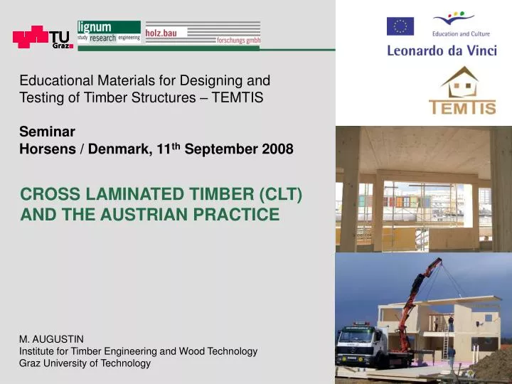
Educational Materials for Designing and Testing of Timber Structures – TEMTIS Seminar. Horsens / Denmark, 11 th September 2008. CROSS LAMINATED TIMBER (CLT) AND THE AUSTRIAN PRACTICE. M. AUGUSTIN Institute for Timber Engineering and Wood Technology Graz University of Technology.

E N D
Educational Materials for Designing and Testing of Timber Structures – TEMTIS Seminar Horsens / Denmark, 11th September 2008 CROSS LAMINATED TIMBER (CLT)AND THE AUSTRIAN PRACTICE M. AUGUSTIN Institute for Timber Engineering and Wood Technology Graz University of Technology
Cross Laminated Timber – Basic idea and Product Utilisation of side-boards Distribution of mechanical propertiesin the log 5-layered CLT-element
CLT –Production volume Arguments PRO CLT: → Massive construction, less layers in theconstruction, buffer for heat and moisture → High degree of prefabrication possible → Easy assembling and short duration for erection → Flexibility of utilisation Arguments CONTRA CLT: → High price Production volume: 2008 About 400.000 m³ (+52 %) → To high amount for the market → Price will decrease (about 20 % in the next three years) Source: Timber Online / 2007
“Austria-House” (2006) Turin / Italy CLT –Examples of erected buildings Building Research Centre Step 2 (2007) Graz / Austria
CLT –Examples of erected buildings Multi-storey building (2001) Vienna / Austria “Wandritsch-Bridge” (1998) St. Lorenzen / Austria
MODULE 1 • Mechanical AspectsStructural AnalysisVerification Procedure • MODULE 3 • GuidelinesBuilding PhysicsLeading Details • MODULE 2 • Connection Technique • MODULE 4 • Development of SystemsArchitectural PotentialCase Studies R&D-Activities concern. CLT – Institutefor Timber Engineering and Wood Technology /holz.bau forschungs gmbH // TUG • AREA 1_SSTC • Shell and Spatial Timber Constructions (SSTC) • TMC using CLT
R&D-Activities concern. CLT – Institutefor Timber Engineering and Wood Technology /holz.bau forschungs gmbH // TUG Limit states Ultimate Limit State Serviceability Limit State Topic: Creep behaviour Topics: “System effects“ “Laminating effects“ Subproject “Creep“ Subproject “Load carrying capacity“(for elements loaded as plates and panels) Objective Load carrying model CLT Deformation factor CLT Further tests: Properties perpendicular to grain Vibration properties of CLT-floors
CLTin standards Eurocode 1995-1-1 Currently no proposals for the verification of CLT-elements → The development of an European standard is initiated by the Austrian Standardisation Organisation (ON). DIN 1052-2004.08 A verification procedere is given in this standard Verification of stresses on each single layer: in accord. with EN 338D → This procedere leads to conservative results because no “homogenisation effects“ are considered !
-35% æ ö 5 2 t 23 - × s ç ÷ × s s m 3 3 h è ø m 15 = @ £ m 1 × f f 0 , 65 f m , d m , d m , d Applied to layered products: e.g. Glulam
Subproject“Load carrying capacity of CLT in bending“ Objective of the research work Method Results of tension tests: ft,0,l,05 = 12,5 N/mm² COVt = 39,4 %
Mean value and COV of edge normal strength fm,c 45,00 18,0% 16,1% 39,4 39,0 40,00 16,0% 37,2 37,3 35,00 14,0% 14,4% 12,5% 30,00 12,0% 25,00 10,0% COV [%] fm,c,mean [N/mm²] 20,00 8,0% 5 # series ‚4u‘ fm,g,mean = 42,4 N/mm² COV = 9,5 % 7,6% 15,00 6,0% 10,00 19 # series ‚1u‘ fm,g,mean = 44,2 N/mm² COV = 20,1 % 4,0% 5,00 2,0% 0,00 0,0% 1 2 3 4 5 6 7 8 mean value Number of lamellas in the outer layers COV Testresults
5% fractile and ksys of edge normal strength fm,c 34,00 1,30 19 # series ‚1u‘ fm,g,05 = 29,0 N/mm² 33,00 32,6 1,25 32,00 31,3 1,20 31,00 1,19 29,8 30,00 1,14 ksys,CLT fm,c,05 [N/mm²] 1,15 29,00 28,00 1,10 1,1 1,09 27,3 27,00 1,05 26,00 1,00 25,00 1,00 1 2 3 4 5 6 7 8 5% fractile Number of lamellas in the outer layers system effect proposal ksys 5 % - quantile valuesand system factor for CLT
including the variation of the base material Load carrying modelfor CLT loaded in bending Beam Model for GLT according to EN 1194:1999 e.g.:
Load carrying modelfor CLT loaded in bending Beam Model for GLT including the variation of the base material
Load carrying modelfor CLT loaded in bending Model for CLT
Load carrying modelfor CLT loaded in bending Model for CLT
ksys kCLT/GLT kh (h = 110 mm, b = 110 mm) a (COVt = 39,4 %) ft,0,l,05 1,1 0,94 1,20 3,15 29,6 26,9 28,6 23,8 12,5 31,3 27,3 29,0 - 12,5 Load carrying modelfor CLT loaded in bending Load carrying model for CLT in bending - based on test results Factor Analy. results Test results
ft,0,l,05 COVt fm,c,05,=4 test results fm,c,05,≥4 calculated [N/mm²] [%] [N/mm²] [N/mm²] presented 12,5 39,4 % 31,3 28,1 New results 1) 26,8 (n = 50) 30,4 % 47,8 45,5 old results (1998) 19,3 (n = 80) ~ 35 % 39,1 2) 42,9 2) 39,4 3) 37,5 1) 5 layer CLT made of solid edge glued panels (spruce); 2) Single result of one 7 layer CLT element (width 2000 mm); 3) Single result of one 9 layer CLT element (width 2000 mm); Load carrying modelfor CLT loaded in bending Proposal of a Beam Model for CLT – Comparison with older data
Verification intechnical approvals Specifications in technical approvals
Comparison ofverification approvals Comparison of verification proposals DIN 1052 Proposal TUG
Determination of stresses inCLT-elements loaded in bending Determination of stresses for CLT Normal stresses Shear stresses Ieff Seff
isotrop spruce CLT 5-layered Determination of deformations ofCLT-elements loaded in bending Determination of deformationsfor CLT Ratio of shear-deformation on the total deflection (single-span beam with uniformly distributed load) 50% 45% 40% 35% 30% Area of utilisation in practice - plate beam Area of utilisation in practice - 25% Ratio wV / wges 20% 15% 10% 5% 0% 10 15 20 25 30 35 Ieff Seff AG,eff k Ratio l / h
Determination of stresses inCLT-elements loaded in bending Effective second moment of area of the cross section Number of layers 3 5 7 Ieff Seff AG,eff k
Determination of stresses inCLT-elements loaded in bending Effective statical moment of the cross section Number of layers 3 5 7 Ieff Seff AG,eff k
Determination of stresses inCLT-elements loaded in bending Effective area of the cross section Number of layers 3 5 7 Ieff Seff AG,eff k
Shear correction factor κ f or CLT cross sections with consideration of the material values in accord. to DIN 1052 6 4,87 4,8 4,11 3,88 3,78 3,73 3,70 3,6 Shear correction factor κ 2,4 1,20 1,2 0 1 3 5 7 9 11 13 Number of layers n Determination of stresses inCLT-elements loaded in bending Shear correction factor Ieff Seff AG,eff k
Determination of stresses inCLT-elements loaded in bending Shear correction factor with values from standards Ieff Seff AG,eff k
60 mm u a Determination of stresses inCLT-elements loaded as panel CLT wall elements under homogeneous shear (shear stiffness) experimental and theoretical solution (doctoral thesis in process: Th. Moosbrugger) - without openings u/a=0.067 ≈ 0.29 practical range board spacing:board width: u = 5 mma = 75 mm Gplate,mean= 229 N/mm² (5 tests, COV = 0.16) 0.8 u/a= 0.067 229 / 750 0.3 - with openings
Creep behaviour ofCLT-elements Results Specimens with two cross sections:GLT and CLT Climate Stress - level GLT CLT Climate 2 Sl.2 - high + 38,5 % Sl.1 - low + 46,5 % Test setup: 4 – point – bending test according to EN 408 Climate 1 Sl.2 - high + 19,3 % Sl.1 - low +41,9 % Proposals for standardisation Futher details tests: Tests with two climates (55%/20°C; 78%/20°C) and two stress levels (about 3 N/mm² and 8 N/mm²) Approximatly values for Plywood
Compression perpendicular to grainof CLT-cubic specimens Ec,90,mean = 500 N/mm² Stiffness fc,90,k = 3,0 N/mm² Strength Test setup: Tests on specimens with different number of layers, position of the board in the log, built-up factor and loading situations
Contact DI Manfred AUGUSTIN Scientific Assistent +43 (0) 316 873-4604 manfred.augustin@lignum.tugraz.at Inffeldgasse 24, A-8010 Graz / Austria THANKS FOR YOUR ATTENTION !