Download
1 / 24
240 likes | 383 Views
Design of an Output Mode Cleaner to Enable DC Readout in the LIGO 40-Meter Interferometer. Marcus Ng Mentor: Alan Weinstein Co-mentor: Robert Ward. Overview. LIGO 40m Gaussian beams OMC design criteria OMC Parameters Geometry Guoy Phase ROC g-factor Finesse Mirror Transmission

E N D
Design of an Output Mode Cleaner to Enable DC Readout in the LIGO 40-Meter Interferometer Marcus Ng Mentor: Alan Weinstein Co-mentor: Robert Ward
Overview • LIGO 40m • Gaussian beams • OMC design criteria • OMC Parameters • Geometry • Guoy Phase • ROC • g-factor • Finesse • Mirror Transmission • Cavity Material • Mode Mismatch • Conclusion
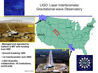
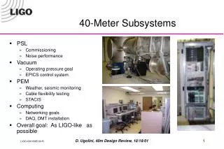
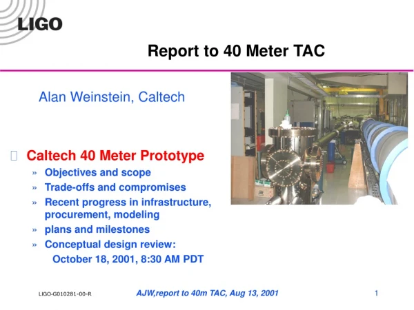
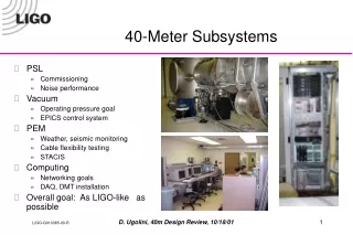
LIGO 40 meter • 40 meter interferometer • Prototype for AdLIGO • Test bed for complex configuration and control systems • DC readout • This summer I worked on design of an OMC and on Mode Matching into the OMC
Gaussian Beams • Laser beams in and propagating between optical cavities have Hermite-Gaussian Transmverse profiles • Transverse Excited Modes (TEM) • LIGO uses TEM00 • Higher Order TEM modes (HOMs) are also present • “Junk light” must be filtered out for effective DC readout Kogelnik & Li 1966
Filtering Junk Light • RF sidebands are used for PDH and Schnupp locking • RF Sidebands also have “junk light” • Sidebands at the 40m are at ±33 and ±166Mhz and HOM • Wavefront curvature differs for each TEM • The OMC is an optical resonator that transmits only the carrier TEM00 mode • It will filter out carrier HOM and RF TEM00 and RF HOM • Purpose of this SURF was to select parameters for the OMC so that it will effectively filter the junk light
Fabry-Perot Optical Cavity • Extreme Sensitivity to resonant frequency • Rejection of all non-resonant frequencies • Light promptly reflects • Some light circulates then transmits out • Cavity length must be ½-integer wavelength of the laser beam for resonance of the TEM00 • At resonance R 0, T1
Filter TEM01 and all higher order TEMs Filter 33 and 166 MHz RF sidebands Filter HOM of RF sidebands Stable cavity Reliable dither-locking Low thermal expansion coeff s.t. PZT only need compensate for less than a few microns Well defined beam waist Well defined location of beam waist Well defined (and suitably minimized) astigmatism Mode matching telescope Angle of incidence large to prevent back reflection to IFO Internal angles large to avoid backreflection and counter-propagating light Design Criteria for the Output Mode Cleaner
Mode Cleaner • Fabry-Perot Cavity with folded geometry • 4-mirror geometry so that reflected light does not return to IFO • Resonant frequency determined by cavity length • Bandwidth determined by finesse
4- v. 3- Mirror Cavity Geometry 4-mirror cavity has half the accidental resonances as a 3 mirror cavity
Guoy Phase • Guoy phase is an additional phase a hermite gaussian acquires beyond a plane wave • Different HOM have different guoy phases • For TEMmn, this phase is equal to (m+n)* Ψtan(Ψ) = LOMC/ZRZR is the Rayleigh range • An optical cavity will resonate for a beam with only one particular round trip phase • It will filter out HOM which have this additional guoy phase • Similarly RF sidebands also have a different phase than the carrier TEM00
Cavity Parameters Radius of Curvature (ROC): • One curved mirror • Influences astigmatism • Determines guoy phase advance of HOM in the cavity g-factor: • Measure of the stability of a cavity • g1 = 1 – LOMC/ROC1, g2 = 1 – LOMC/ROC2 • Stable Cavity for 0 ≤ g1g2 ≤ 1 • Treat cavity as half symmetric resonator • gfac = 1 – LOMC/(2*ROC)
Beam Waist Beam Waist = 0.3797 mm for ROC = 1.000 m
Selecting a ROC = 1.000 m g-factor = 0.775 Cavity Length 45 cm
Cavity Parameters Finesse: • Higher finesse corresponds to sharper, finer resonant peak therefore more suppression of HOM and RF sidebands • fin = FSR/FWHM • fin = π√((1-δloss)/δloss) • δloss = 4*Lossmirr + 2*Tmirr
Mode Matching • After finalizing OMC parameters, we had to design a system to mode match the input beam into the OMC • We will construct a Mode Matching Telescope (MMT)
Mode Mismatch Mismatch in Waist Location Mismatch in Waist Size ((λ d) / (2 πω0))2 (ω0' / ω0 - 1)2 coupling coefficients for each type of mismatch MM2 = ((λ d) / (2 πω0))2 + (ω0' / ω0 - 1)2
OMMT • Two Curved Mirrors • Variable Telescope Length • ROCs selected “off-the-shelf” from catalog • Selection Criteria: Minimize Mode Mismatch Above Design by Mike Smith
ROC1 = 618.4 mm ROC2 = 150.0 mm wOMC = 0.37965 mm wETM = 5.2422 mm wITM = 3.0266 mm wBS = 3.034 mm wSRM = 3.0355 mm wOMMT = 3.0355 mm
Conclusion • We have designed parameters for an OMC to filter out junk light from the output beam of the 40m IFO • We have designed an optical system for mode matching into the OMC • The system will be constructed and commissioned in the coming months
Alan Weinstein Rana Adhikari Osamu Miyakawa Caltech Robert Ward Keita Kawabe Mike Smith NSF Special thanks to: