Download
1 / 19
190 likes | 303 Views
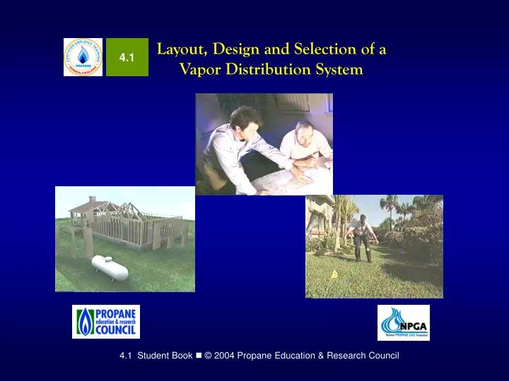
4.1. Layout, Design and Selection of a Vapor Distribution System. CETP Program Disclaimer. Consult local jurisdictions for applicable codes, standard and legal requirements This material is not an exhaustive treatment of the subject

E N D
4.1 Layout, Design and Selection of a Vapor Distribution System
CETP Program Disclaimer • Consult local jurisdictions for applicable codes, standard • and legal requirements • This material is not an exhaustive treatment of the subject • and does not preclude other procedures to enhance safe • LP-gas operations • This publication is not intended nor should it be construed • to • Set forth procedures which are the general custom or • practice in the propane industry • Establish the legal standards of care owed by • propane distributors to their customers • Prevent the reader from using different methods to • implement applicable codes, standards or legal require- • ments.
CETP Program Disclaimer • This training material was designed to be used as a • resource only and does not replace federal, state, local, • or company safety rules. • The user of this material is solely responsible for the • method of implementation. • The Propane Education and Research Council, the • National Propane Gas Association and Industrial Training • Services, Inc. assume no liability for reliance on the • contents of this training material. • Issuance of this material is not intended to nor should it be • construed as an undertaking to perform services on be- • half of any party either for their protection or for the • protection of third parties.
Learning Aids—These margin notes are provided to help you identify sources, take precautions, or give guidance on your job. Symbols Warning: Important precaution that you should always remember when performing the identified task. Tools: This task requires special tools or procedures. PPE: This is a task that requires personal protection equipment. Paper Work or Forms: This task should be documented on your company’s forms for compliance or legal reasons. Safety Procedure: For your safety special precautions and safety guidelines apply to this task or operation of equipment. Company S.O.P. : Follow your company’s Standard Operating Practices (or Procedures). Ifyou’re not sure of your company’s policy, check with your supervisor.
Electrical Hazard: This task involves an electrical hazard. Lockout and Tagout procedures must be followed. Explosive/Fire Hazard: This task involves a fire or explosion hazard. Use appropriate precautions. Lockout and Tagout procedures may apply. Technical Tips: This technique may be very useful as you do a task. Technical Tip The National Fire Protection Association: References to sections of the LP-Gas Codes and Standards. NFPA 54 Or NFPA 58 U.S. Department of Transportation: DOT has regulatory authority, both interstate and intrastate, over the transportation of hazardous materials. References to Title 49, Code of Federal Regulations. Department of Labor: (OSHA) administers federal employee safety and health regulations.
4.1.1 Using Architectural and Construction Drawings Construction drawings used for designing and installing vapor distribution systems may be as simple as a quick sketch with lengths of piping runs penciled in, or they may be detailed architectural scale drawings consisting of several pages. • In this module you will learn to: • Identify architectural and construction drawings
Identifying Architectural and Construction Drawings The need for architectural and construction drawings depends on how simple or complex the installation. In some cases, a simple sketch will work as in Figure 1. In others, complex drawings may be needed. Figure 1. Piping Sketch
Architectural Drawings Detailed architectural drawings are scale drawings that use fractions of an inch to represent 1 foot of the actual building. To determine the accurate location of gas appliances or gas distribution runs, an architectural scale ruler that corresponds to the scale of the drawing is used.
Architectural Drawings Figure 2. House Floor Plan Scale Drawing (Proportionally reduced from original size)
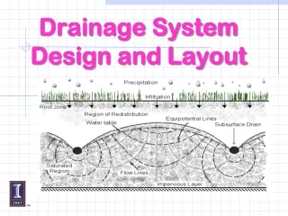
Plot Plans and Topographical Drawings Figure 3. Plot Plan and Topographic Drawing
Plot Plans and Topographical Drawings • Detailed plot plans and topographic (elevation) drawings provide useful information that can include: • Practical and safe locations for propane tanks and cylinders—especially underground tanks • Landscaping, sprinkler systems, and septic system components that must be avoided when setting the propane tank and running the underground gas distribution lines
Elevation Drawings and Floor Plans Figure 4. Front Elevation and Floor Plan
Elevation Drawings and Floor Plans From the elevation plan, a gas distribution designer or installer can determine if gas distribution lines can be run in either the attic or basement. Planned locations of gas appliances and the lengths of horizontal and vertical pipe runs can also be determined.
Schedules and Details Schedules are lists of components used to furnish or finish-out a building. Figure 5. Gas Appliance Schedule
Schedules and Details Figure 6. Hydronic Heating System Detail
Other Specialized Drawings Isometric drawings illustrate 3-dimensional relationships. They are useful because they help in visualizing horizontal and vertical piping runs. Figure 7. Gas Piping Isometric Drawing
Other Specialized Drawings Figure 8. Pipe/Tubing Fittings Drawing Symbols
Other Specialized Drawings Pipe/Tubing Fittings Drawing Symbols
Time to See If You Got the Key Points of This Module… • Complete the Review on page 7. • See if you are ready for the Certification Exam by checking off the performance criteria on page 8.