Download
1 / 41
410 likes | 521 Views
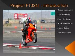
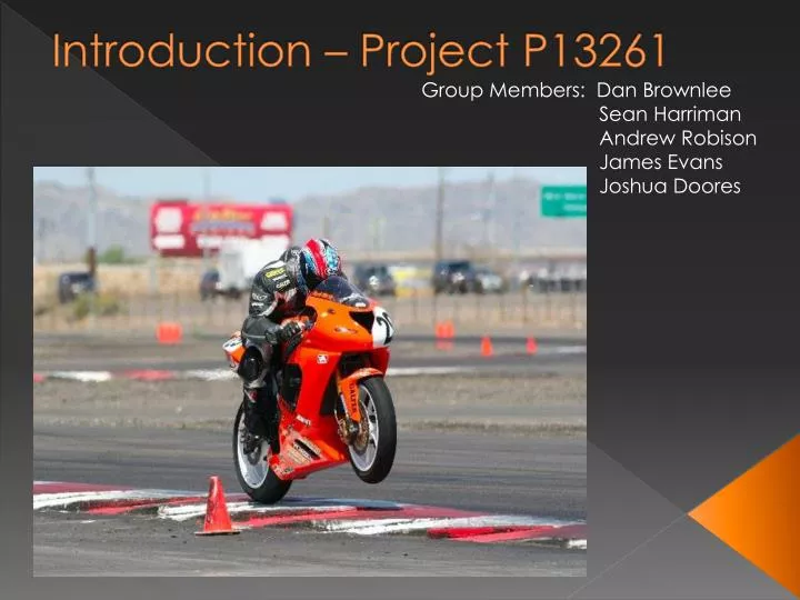
Introduction – Project P13261 . Group Members: Dan Brownlee Sean Harriman Andrew Robison James Evans Joshua Doores. Mechanical Diagram. A Frame.

E N D
Introduction – Project P13261 Group Members: Dan Brownlee Sean Harriman Andrew Robison James Evans Joshua Doores
Test Plan • 3 tests • Duty cycle testing wheel lift • Duty cycle testing wheel slip • Optional Manual throttle input
Lab View • Displays Motor and Wheel RPM • Displays Throttle Signal and modified signal • “Driver Prompts” (Ideal points where shifting should occur) • Two test buttons, one for each duty cycle, and a switch to allow for manual throttle. • Data transferred via USB from the DAQ to host computer and exported into excel at the end of the data cycle.
Micro-controller Selection Starter Board with DSPIC33F Series Micro-controller.
Maximum Frequency Determination Matlab Code determining the maximum frequency we would need
Inputs/Outputs Determination Master Clear (NC) Analog Input 1: Front Fork Sensor - Linear Potentiometer Analog Input 2: Throttle – Linear Potentiometer Analog Input 3: Accelerometer, On board potentiometer, Thermal Couple? Output Compare: PWM Output Input Capture Inputs: Front Wheel Hall Effect, Rear wheel Hall Effect. Other I/O Pins: SPI, I2C, UART (USB) Interrupt Pin: Emergency Stop Button, Mode Button, Data Output Button Grayed in Pins can handle 5V.
Notes on Pin Initialization • Any I/O pins not being used should be configured as an output and driven to a logic low state. Alternately, a 1K-10K ohm resistor connected between VSS and the unused pin would drive the output low. • VDD and VSS are attached to the board and will be connected to the power supply at a voltage level according to what the board power spec is. (Can handle a 9V power supply. Voltage regulators for 3.3V and 5V operation exist) • Not every pin can handle 5V • Some of the pins will be used by the board, for example the external oscillator inputs. • Configure Timer 2/3 as 2 independent 16-bit timers. Are used by multiple I/O functions; such as the input capture and output capture.
Flowcode/Pseudo code Link to Visio Block Diagram of Pseudo code
Known Issues to be Solved • 1.) This micro-chip is run on 3.3V, and most of the pins can only handle a 3.3V signal. (Some are 5V tolerant). Do we need to drop the voltage to the input with a resistor? Does the board have a voltage regulator that would drop the voltage to the input? • 2.) Not sure how the IVT works. Only one interrupt pin, but is it useable by many interrupts? • 3.) Sampling Frequency Determination – Still need to determine at what frequency we will be sampling our analog inputs.
Electrical System Overview • Main Components • Batteries • Primary (72VDC) • Secondary (12VDC) • Motor • Brushed DC • Motor Controller • DC-to-DC Converters • Microcontroller • Ignition Switch • Peripherals (5VDC) • Potentiometers • Hall Effect Sensors • Switches • Circuit Protection • Fuses • Diodes • Circuit Breakers • Optoisolators • Safety • Emergency Stop • Kill Switch
Electrical System Functional Overview • System Functions • Store High Voltage (HV) and route current to electric motor to propel motorcycle • Maintain OEM-type motorcycle battery voltage used to power microcontroller and motor controller • Control rear wheel spin and front wheel lift by modifying the throttle input signal to the motor controller • Isolate HV battery from all HV components for safer operability and serviceability
Electrical System Bill of Materials (BOM*) *Only includes parts not listed in the System Specifications to prevent redundancy.
Customer Needs • Meets all TTXGP safety regulations • Be safely controlled, Serviced, Modified, and Troubleshot • Conform to all TTXGP race regulations • Integrate into an existing rolling chassis • Be ready for integration by the end of winter 2012 • Adjustability to be able to be used with multiple frames • Must fit within available club space and be easily stored • Minimize electrical energy consumption • Display drive train and vehicle parameters • Provides Driver Prompts • Maximize Acceleration
Feasibility Analysis • Shaft Life • Bearing Life • Stress Strain in A-Frame • Component Compatibility • Low Pass Filter Operation • Controller/Micro Capabilities
Electrical System Wiring Diagram Rear WSS & RLR Mounting Location Front WSS Mounting Location Return
Electrical System Wiring Diagram Solenoid Circuit Breaker Return
Electrical System Wiring Diagram Motor Controller Return
Electrical System Wiring Diagram Front Suspension Linear Potentiometer Return
Electrical System Wiring Diagram DC Motor (supplied) Motor Curves @ 72VDC Return