Download
1 / 70
710 likes | 969 Views
ARM instruction set. ARM versions. ARM assembly language. ARM programming model. ARM memory organization. ARM data operations. ARM flow of control. ARM versions. ARM architecture has been extended over several versions. We will concentrate on ARM7. ARM assembly language.

E N D
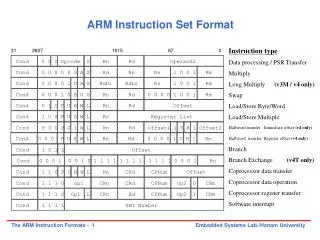
ARM instruction set • ARM versions. • ARM assembly language. • ARM programming model. • ARM memory organization. • ARM data operations. • ARM flow of control.
ARM versions • ARM architecture has been extended over several versions. • We will concentrate on ARM7.
ARM assembly language • Fairly standard assembly language: LDR r0,[r8] ; a comment label ADD r4,r0,r1
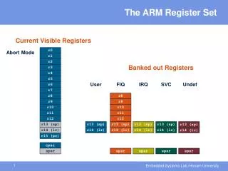
N Z C V ARM programming model r0 r8 r1 r9 0 31 r2 r10 CPSR r3 r11 r4 r12 r5 r13 r6 r14 not be overwritten r7 r15 (PC) Current program status register ARM is a load-store architecture Top 4 bits; negative, zero, carry, overflow
Endianness • Relationship between bit and byte/word ordering defines endianness: bit 31 bit 0 bit 0 bit 31 byte 3 byte 2 byte 1 byte 0 byte 0 byte 1 byte 2 byte 3 little-endian big-endian
ARM data types • Word is 32 bits long. • Word can be divided into four 8-bit bytes. • ARM addresses can be 32 bits long. • Address refers to byte. • Address 4 starts at byte 4. • Can be configured at power-up as either little- or bit-endian mode.
ARM status bits • Every arithmetic, logical, or shifting operation sets CPSR bits: • N (negative) (2’s comp.), Z (zero), C (carry), V (overflow). • Examples: • -1 + 1 = 0: NZCV = 0101 (0xffffffff + 0x00000001). • 231-1+1 = -231: NZCV = 1001 (0xffffffff + 0xffffffff + 0x00000001).
ARM data instructions • Basic format: ADD r0,r1,r2 • Computes r1+r2, stores in r0. • Immediate operand: ADD r0,r1,#2 • Computes r1+2 (imm. oprd.), stores in r0.
ADD, ADC : add (w. carry) SUB, SBC : subtract (w. carry) RSB, RSC : reverse subtract (w. carry) MUL, MLA : multiply (and accumulate) AND, ORR, EOR(bw xor) BIC : bit clear LSL, LSR : logical shift left/right ASL, ASR : arithmetic shift left/right ROR : rotate right RRX : rotate right extended with C ARM data instructions
Examples • ADD r0, r1, r2 • R0 = R1 + R2 • SUB r5, r3, #10 • R5 = R3 − 10 • RSB r2, r5, #0xFF00 • R2 = 0xFF00 − R5
Data operation varieties • Logical shift: • fills with zeroes. • Arithmetic shift: • fills with ones. • RRX performs 33-bit rotate, including C bit from CPSR above sign bit.
Branch instructions • When executing the instruction, the processor:shifts the offset left two bits, sign extends it to 32 bits, and adds it to PC. • Execution then continues from the new PC, once the pipeline has been refilled. • The "Branch with link" instruction implements a subroutine call bywriting PC-4 into the LR of the current bank. • i.e. the address of the next instruction following the branch with link (allowing for the pipeline). • To return from subroutine, simply need to restore the PC from the LR: • • MOV pc, lr • • Again, pipeline has to refill before execution continues. • The "Branch" instruction does not affect LR.
Data processing Instructions • Largest family of ARM instructions, all sharing the same instruction format. Contains: • Arithmetic operations • Comparisons (no results - just set condition codes) • Logical operations • Data movement between registers • This is a load / store architecture • • These instructionsonly work on registers, NOT memory. • They each perform a specific operation on one or two operands. • First operand always a register - Rn • Second operand sent to the ALU via barrel shifter.
Arithmetic Operations • Operations are: • ADD operand1 + operand2 • ADC operand1 + operand2 + carry • SUB operand1 - operand2 • SBC operand1 - operand2 + carry -1 • RSB operand2 - operand1 • RSC operand2 - operand1 + carry – 1 • Syntax: • <Operation>{<cond>}{S} Rd, Rn, Operand2 • Examples • ADD r0, r1, r2 • SUBGT r3, r3, #1 • RSBLES r4, r5, #5
Comparisons • The only effect of the comparisons is to • UPDATE THE CONDITION FLAGS. Thus no need to set S bit. • Operations are: • CMP operand1 - operand2, but result not written • CMN operand1 + operand2, but result not written • TST operand1 AND operand2, but result not written • TEQ operand1 EOR operand2, but result not written • Syntax: • <Operation>{<cond>} Rn, Operand2 • Examples: • CMP r0, r1 • TSTEQ r2, #5
Logical Operations • Operations are: • AND operand1 AND operand2 • EOR operand1 EOR operand2 • ORR operand1 OR operand2 • BIC operand1 AND NOT operand2 [ie bit clear] • Syntax: • <Operation>{<cond>}{S} Rd, Rn, Operand2 • Examples: • AND r0, r1, r2 • BICEQ r2, r3, #7 • EORS r1,r3,r0
Data Movement • Operations are: • MOV operand2 • MVN NOT operand2 • Note that these make no use of operand1. • Syntax: • <Operation>{<cond>}{S} Rd, Operand2 • Examples: • MOV r0, r1 • MOVS r2, #10 • MVNEQ r1,#0
Second Operand :Shifted Register • The amount by which the register is to be shifted is contained in either: • the immediate 5-bit field in the instruction • NO OVERHEAD • Shift is done for free - executes in single cycle. • the bottom byte of a register (not PC) • Then takes extra cycle to execute • ARM doesn’t have enough read ports to read 3 registers at once. • Then same as on other processors where shift is separate instruction. • If no shift is specified then a default shift is applied: LSL #0 • i.e. barrel shifter has no effect on value in register.
Second Operand :Using a Shifted Register • Using a multiplication instruction to multiply by a constant means firstloading the constant into a register and then waiting a number ofinternal cycles for the instruction to complete. • A more optimum solution can often be found by using some combinationof MOVs, ADDs, SUBs and RSBs with shifts. • Multiplications by a constant equal to a ((power of 2) 1) can be done in one cycle. • Example: r0 = r1 * 5 • Example: r0 = r1 + (r1 * 4) • ADD r0, r1, r1, LSL #2 • Example: r2 = r3 * 15 • Example: r2 = r3 * 15 * 7 • Example: r2 = r3 * (16 - 1) * (8 - 1) • RSB r2, r3, r3, LSL #4 ; r2 = r3 * 15 • RSB r2, r2, r2, LSL #3 ; r2 = r2 * 7
Second Operand :Immediate Value • There is no single instruction which will load a 32 bit immediate constantinto a register without performing a data load from memory. • All ARM instructions are 32 bits long • ARM instructions do not use the instruction stream as data. • The data processing instruction format has 12 bits available for • operand2 • If used directly this would only give a range of 4096. • Instead it is used to store 8 bit constants, giving a range of 0 - 255. • These 8 bits can then be rotated right through an even number ofpositions (ie RORs by 0, 2, 4,..30). • This gives a much larger range of constants that can be directly loaded,though some constants will still need to be loaded from memory.
Second Operand :Immediate Value • These can be loaded using, for example: • MOV r0, #0x40, 26 ; => MOV r0, #0x1000 (ie 4096) • To make this easier, the assembler will convert to this form for us ifsimply given the required constant: • MOV r0, #4096 ; => MOV r0, #0x1000 (ie 0x40 ror 26) • The bitwise complements can also be formed using MVN: • MOV r0, #0xFFFFFFFF ; assembles to MVN r0, #0 • If the required constant cannot be generated, an error will be reported.
Loading full 32 bit constants • Although the MOV/MVN mechansim will load a large range of constantsinto a register, sometimes this mechansim will not generate the required constant. • Therefore, the assembler also provides a method which will load ANY 32 bit constant: • LDR rd, =numeric constant • If the constant can be constructed using either a MOV or MVN then thiswill be the instruction actually generated. • Otherwise, the assembler will produce an LDR instruction with a PC-relativeaddress to read the constant from a literal pool (a lookup table). • LDR r0,=0x42 ; generates MOV r0,#0x42 • LDR r0,=0x55555555 ; generate LDR r0,[pc, offset to literalpool] • As this mechanism will always generate the best instruction for a givencase, it is the recommended way of loading constants.
Multiplication Instructions • The Basic ARM provides two multiplication instructions. • Multiply • MUL{<cond>}{S} Rd, Rm, Rs ; Rd = Rm * Rs • Multiply Accumulate - does addition for free • MLA{<cond>}{S} Rd, Rm, Rs,Rn ; Rd = (Rm * Rs) + Rn • Restrictions on use: • Rd and Rm cannot be the same register • Can be avoid by swapping Rm and Rs around. This works because multiplication is commutative. • Cannot use PC. • Operands can be considered signed or unsigned • MLA r0,r1,r2,r3 • sets r0 to the value r1 x r2 + r3.
Multiplication Implementation • The ARM makes use of Booth’s Algorithm to perform integer multiplication. • On non-M ARMs this operates on 2 bits of Rs at a time. • For each pair of bits this takes 1 cycle (plus 1 cycle to start with). • However when there are no more 1’s left in Rs, the multiplication will early-terminate. • Example: Multiply 18 and -1 : Rd = Rm * Rs • Note: Compiler does not use early termination criteria todecide on which order to place operands.
Extended Multiply Instructions • M variants of ARM cores contain extended multiplicationhardware. This provides three enhancements: • An 8 bit Booth’s Algorithm is used • Multiplication is carried out faster (maximum for standardinstructions is now 5 cycles). • Early termination method improved . • 64 bit results can now be produced from two 32bit operands • Higher accuracy. • Pair of registers used to store result.
Multiply-Long andMultiply-Accumulate Long • Instructions are • MULL which gives RdHi,RdLo:=Rm*Rs • MLAL which gives RdHi,RdLo:=(Rm*Rs)+RdHi,RdLo • However the full 64 bit of the result now matter (lowerprecisionmultiply instructions simply throws top 32bits away) • Need to specify whether operands are signed or unsigned • Therefore syntax of new instructions are: • UMULL{<cond>}{S} RdLo, RdHi, Rm, Rs • UMLAL{<cond>}{S} RdLo, RdHi, Rm, Rs • SMULL{<cond>}{S} RdLo, RdHi, Rm, Rs • SMLAL{<cond>}{S} RdLo, RdHi, Rm, Rs • Not generated by the compiler. • Warning : Unpredictable on non-M ARMs.
Register indirect addressing in the ARM, and Computing an absolute address using the PC A register holds a frame pointer (fp) that points to the top of the frame; elements within theframe are accessed using offsets from fp. The assembler syntax [fp,#-n] is used totake the nth location from fp. By adding or subtracting to thePC a constant equal to the distance between the current and the desired location, we can generate the desiredaddress without performing a load. The ARM programming system provides an ADRpseudo-operation to simplify this step. Thus, if we give location0x100 the name FOO, we can use the pseudo-operation ADR r1, FOO r15 PC
C Assignments in ARM Instructions • The statement x = (a + b) - c; r0 for a, r1 for b, r2 for c, and r3 for x. • It uses a frame pointer tohold the variables: a is at -24, b at -28, c at -32, and x at -36: • ldr r0, [fp, #-24] • ldr r1, [fp, #-28] • add r0, r0, r1 • ldr r2, [fp, #-32] • rsb r3, r2, r0 • str r3, [fp, #-36]
Load / Store Instructions • The ARM is a Load / Store Architecture: • Does not support memory to memory data processing operations. • Must move data values into registers before using them. • This might sound inefficient, but in practice isn’t: • Load data values from memory into registers. • Process data in registers using a number of data processinginstructions which are not slowed down by memory access. • Store results from registers out to memory. • The ARM has three sets of instructions which interact with main memory. These are: • Single register data transfer (LDR / STR). • Block data transfer (LDM/STM). • Single Data Swap (SWP).
Single register data transfer • The basic load and store instructions are: • Load and Store Word or Byte • LDR / STR / LDRB / STRB • ARM Architecture Version 4 also adds support for halfwords and signed data. • Load and Store Halfword • LDRH / STRH • Load Signed Byte or Halfword - load value and sign extend it to 32 bits. • LDRSB / LDRSH • All of these instructions can be conditionally executed by inserting the appropriate condition code after STR / LDR. • e.g. LDREQB • Syntax: • <LDR|STR>{<cond>}{<size>} Rd, <address>
Addressing modes: • register indirect : LDR r0,[r1] • r1 holds the memory location (address) • with second register : LDR r0,[r1,-r2] • Address given by r1 – r2 • with constant : LDR r0,[r1,#4] • loads r0 from the address r1 + 4
Load and Store Word or Byte: Base Register • The memory location to be accessed is held in a base register • STR r0, [r1] ; Store contents of r0 to location pointed to ; by contents of r1. • LDR r2, [r1] ; Load r2 with contents of memory location ; pointed to by contents of r1.
Load and Store Word orByte:Offsets from the Base Register • As well as accessing the actual location contained in the base register,these instructions can access a location offset from the base register pointer. • This offset can be • An unsigned 12-bit immediate value (ie 0 - 4095 bytes). • A register, optionally shifted by an immediate value • This can be either added or subtracted from the base register: • Prefix the offset value or register with ‘+’ (default) or ‘-’. • This offset can be applied: • before the transfer is made: Pre-indexed addressing • optionally auto-incrementing the base register, by postfixing the instruction with an ‘!’. • after the transfer is made: Post-indexed addressing • causing the base register to be auto-incremented.
Load and Store Word or Byte: Pre-indexed Addressing • To store to location 0x1f4 instead use: STR r0, [r1,#-12] • To auto-increment base pointer to 0x20c use: STR r0, [r1, #12]! • If r2 contains 3, access 0x20c by multiplying this by 4: • STR r0, [r1, r2, LSL #2]
Load and Store Word or Byte:Post-indexed Addressing • To auto-increment the base register to location 0x1f4 instead use: • STR r0, [r1], #-12 • If r2 contains 3, auto-incremenet base register to 0x20c by multiplying this by 4: • STR r0, [r1], r2, LSL #2
Offsets for Halfword andSigned Halfword / Byte Access • The Load and Store Halfword and Load Signed Byte or Halfwordinstructions can make use of pre- and post-indexed addressing in muchthe same way as the basic load and store instructions. • However the actual offset formats are more constrained: • The immediate value is limited to 8 bits (rather than 12 bits) giving an offset of 0-255 bytes. • The register form cannot have a shift applied to it.
Effect of endianess • The ARM can be set up to access its data in either little or big endian format. • Little endian: • Least significant byte of a word is stored in bits 0-7 of an addressed word. • Big endian: • Least significant byte of a word is stored in bits 24-31 of an addressed word. • This has no real relevance unless data is stored as words and thenaccessed in smaller sized quantities (halfwords or bytes). • Which byte / halfword is accessed will depend on the endianess of the system involved.
Block Data Transfer • The Load and Store Multiple instructions (LDM / STM) allow betweeen1 and 16 registers to be transferred to or from memory. • The transferred registers can be either: • Any subset of the current bank of registers (default). • Any subset of the user mode bank of registers when in a priviledged mode (postfix instruction with a ‘^’).
Block Data Transfer • Base register used to determine where memory access should occur. • Different addressing modes allow increment and decrement inclusive orexclusive of the base register location. • Base register can be optionally updated following the transfer (appending with an ‘!’). • Lowest register number is always transferred to/from lowest memory location accessed. • These instructions are very efficient for • Saving and restoring context • For this useful to view memory as a stack. • Moving large blocks of data around memory • For this useful to directly represent functionality of the instructions.