Download
1 / 48
500 likes | 820 Views
Analog Electronics Class 4 CMRR, PSRR, Vcm Range, Output Swing. Oct 10, 2011. Common Mode Voltage Range. Common Mode Voltage Def:. REAL WORLD Inputs. Typical Bipolar or JFET Input (not rail-to-rail). Simplified schematic of OPA827 input stage. Simulate Vcm Range. Simulate Vcm Range.

E N D
Analog Electronics Class 4CMRR, PSRR, Vcm Range, Output Swing Oct 10, 2011
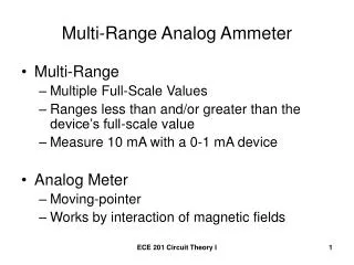
Common Mode Voltage Range
Simulate Vcm Range Simulated and data sheet don’t always match
MOSFET Charge Pump (rail-to-rail) • Supplies a small current to input • GBW = 50MHz, Charge Pump Freq=10MHz
MOSFET Zero Drift (rail-to-rail) With Offset Correction No Offset Correction
Common Mode Rejection Ratio
CMRR Specification CMRR(dB) = 20 Log (ΔVosi / Δ Vcm) (data sheet) CMRR(Linear-Gain) = 10(CMRR(dB)/20) (solve for linear gain) CMRR(Linear-Gain) = ΔVosi / Δ Vcm
Note: Vos is defined for this condition. Vcm = Vs/2 Vs/2 = GND in this case Note: Vos is affected by Vcm. Vcm = Vs/2 + 12V
AC CMRR Example OPA170 Vcm = Vin Vcm = 0V Vcm = Vsupply / 2
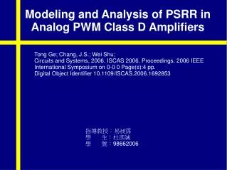
Power Supply Rejection Ratio
AC PSRR Simulation ExampleOPA170 Set up the AC source. 1V @ 1kHz in this case.
Output Stage Considerations
Classic Output Stage • Common-emitter output • Current source driver • Headroom set by VBE+VCESAT • Unity Gain
OPA827 OPA827 OPA827 – Classic Output
R-to-R Output Stage • Common Collector or Common Drain • Headroom set by VCESAT
R-to-R Output Stage • Common Collector or Common Drain • Headroom set by VCESAT • Value of RLOAD affects AOL
1. Calculate and simulate the output offset for the following circuits.
2. Calculate and simulate the swing to the rail limit for the following circuits.
3. Calculate and simulate the effect of the ac source on the power supply .