Download
1 / 59
590 likes | 648 Views
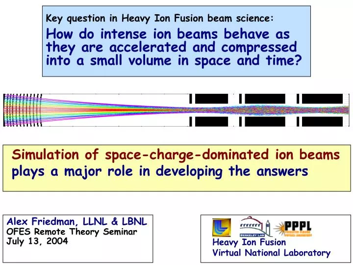
Simulation of space-charge-dominated ion beams plays a major role in developing the answers. Key question in Heavy Ion Fusion beam science: How do intense ion beams behave as they are accelerated and compressed into a small volume in space and time?. Alex Friedman, LLNL & LBNL

E N D
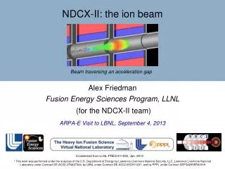
Simulation of space-charge-dominated ion beams plays a major role in developing the answers Key question in Heavy Ion Fusion beam science:How do intense ion beams behave as they are accelerated and compressed into a small volume in space and time? Alex Friedman, LLNL & LBNL OFES Remote Theory Seminar July 13, 2004 Heavy Ion Fusion Virtual National Laboratory
Outline • Introduction • Present-day experiments • Fundamental beam science • Future experiments & discussion … and along the way … New computational methods and models that have broad applicabilty
beam ions background ions electrons target Beams are non-neutral plasmas with dynamics dominated by long-range space-charge forces They are collisionless and have “long memories” — must follow ion distribution from source to target Beam modeling program is ~ 2/3 simulation, ~ 1/3 analytic theory; here we discuss the former “Multiscale, multispecies, multiphysics” - ions encounter: • Good electrons: neutralization by plasma aids compression, focusing • Bad electrons: stray “electron cloud” and gas can afflict beam
In driver -12 -11 -10 -9 -8 -7 -6 -5 -4 -3 -2 -1 0 Length scales: • electron gyroradius in magnet ~ 10 mm • lD,beam ~ mm • beam radius ~ cm • lattice period ~ m • beam length ~ 1-10 m • machine length ~ km In chamber Time and length scales in driverandchamberspan a wide range Time scales: depressed betatron betatron t electron drift pb out of magnet » transit lattice thru electron period fringe beam cyclotron pulse fields residence in magnet log of timescale (s) pulse beam t pe residence t pi t pb
Beam starts with a small 6D phase space volume; applications demand that it grow only modestly • Present-day (e.g., “HCX”) beams, roughly: • Total ions N ~ 5 x 10¹² (K+) in ~ 5 ms (0.2 Amperes) • line charge density ~ 0.1 C/m • number density n ~ 1015 m-3 • kinetic energy Ek ~ 1 MeV (v/c ~ 0.005) • temperature Teff ~ 0.2 eV at 5-cm source, ~ 20 eV in transport section • beam radius r ~ 1 cm • T and r translate to initial transverse phase space area (“normalized emittance”) ~ 0.5 -mm-mr • Downstream, in a 2-GeV driver: • increases ~ 5x in accelerator, then 20x in final compression • Have “headroom” for phase space area to grow by ~ factor of 10 (less is always better)
Particle-in-Cell (PIC) is main tool; challenges are addressed by new computational capabilities • resolution challenges (Adaptive Mesh Refinement-PIC) • dense plasmas (implicit, hybrid PIC+fluid) • short electron timescales (large-Dt advance) • electron-cloud & gas interactions (new “roadmap”) • slowly growing instabilities (f for beams) • beam halo (advanced Vlasov)
Track beam ions consistently along entire system Ion source & injector Accelerator Buncher Final focus Chamber transport Target HIF-VNL’s approach to self-consistent beam simulation employs multiple tools Study instabilities, halo, electrons, ..., via coupled detailed models
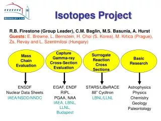
II. Simulations and theory support present-day ion beam experiments Heavy Ion Fusion Virtual National Laboratory Injectors HCX NTX Simulations & Theory
Injectors Research on high-brightness sources & injectors uses test stands, including STS-500 at LLNL
Fine grid patch around source & tracking beam edge high resolution low resolution + AMR 0.4 0.2 0.0 0.1 0.2 0.3 0.4 Particle simulation & adaptive mesh refinement (AMR) are married at last! Application to HCX triode in axisymmetric (r,z) geometry This example: ~ 4x savings in computational cost (in other cases, far greater savings) eN (p-mm.mrad) Z(m) (Simulations by J-L. Vay)
Adaptive Mesh Refinement requires automatic generation of nested meshes with “guard” regions Simulation of diode using merged Adaptive Mesh Refinement & PIC
Phase space at end of diode Warp simulation Experimental data Experiment 10 Theory x -10 -50 0 50 -50 0 50 x (mm) x (mm) (Simulations by I. Haber, J-L. Vay, D. P. Grote) WARP simulations of STS-500 experiments significantly advance the state of the art Rise time Current (mA) at Faraday cup 6 4 2 0 0 2 4 time (s) Result depends critically on mesh refinement 5-cm-radius K+ alumino-silicate source
7.5 X (mm) -7.5 0.5 1.0 0. 1.5 Z (m) WARP simulations guided the physics design of the beamlet-merging experiment on STS-500 119 beamlets, ITotal = 0.07 A, Efinal = 400 keV Normalized emittance RZ and XY for synthesis; 3D for validation (Simulations by D. Grote)
HCX ESQ injector Marx 10 Electrostatic quads ESQ injector 4 Magnetic quads matching diagnostics 10 ES quads diagnostics diagnostics The High Current Experiment enables studies of beam dynamics and stray-electron physics K+ Beam ~ 0.2 - 0.5 A 1 - 1.7 MeV ~ 5 s
Time-dependent 3D simulations of HCX electrostatic quadrupole injector reveal beam-head behavior From a WARP movie by J-L. Vay; see http://hif.lbl.gov/theory/simulation_movies.html
Matching section compresses beam significantly before it enters the HCX transport line (frame from a WARP movie by J-L. Vay)
A common experimental diagnostic is based on slit-scanners Two-Slit Emittance Scan: Measures the beam phase space projection perpendicular to the slits: slit 1 selects for position x slit 2 selects for “slope” x px/pz detector Crossed-Slit Intensity Map: Measures the distribution of beam current density in the transverse plane The 4D distribution ƒ(x,y,x,y) is not uniquely determined by a small number of such 2D scans; “synthesize” an ƒ tomographically
Experiment y x y y x x y y WARP y x x x Hollowing is a common feature Some HCX runs use initial conditions derived from slit-scan data Simulations initialized this way agree only roughly w/expt need better data (Simulations by C.Celata)
y v Slit Scintillator u x Isosurface upon which ƒ(x,y,x) = 0.3 ƒmax shadow of “bridge” across slit face-on (xy) view rotated to right “Optical slit” diagnostic is yielding unprecedented information about the HCX beam particle distribution This scanner measures f(x,y,x) It can be “gated” in time
Neutralization competes with stripping in the target chamber NTX
The Neutralized Transport Experiment (NTX) enables studies of beam neutralization and focusing 4 magnetic quadrupoles MEVVA source (plasma plug) Non-neutralized FWHM = 6.6 mm Plasma plug + volume plasma RF source (volumetric) Scintillating glass diagnostic FWHM = 1.5 mm
Variation of beam image vs. quadrupole strength shows good agreement of NTX data with WARPxy simulations Images at entrance to neutralized transport section Experiment Simulation DQ1= ± 5% DQ2= ± 2% DQ3= ± 2% DQ4= ± 2% Nominal energy and fields
LSP simulations of NTX transport are now being initialized with the measured 4D particle distribution • EM, 3D cylindrical geom., 8 azimuthal spokes • 3 eV plug 3x109 cm-3, volume plasma 1010 cm-3 LSP fluence at target Carsten Thoma, et. al.
scaled exp’ts Small-scale experiments are studying long-path transport physics Princeton’s Paul Trap Simulator Experiment Ion bunch confined in oscillating electric quadrupole field; equivalent to 1000’s of lattice periods Univ. of Maryland Electron Ring (UMER)
Q3 Q1 Q4 Scaled electron ring at U. MD is simulated using WARP Experiment (top) vs. WARP simulation (bottom) The rings are due to edge lensing
Heavy Ion Fusion Virtual National Laboratory III. Fundamental beam science studies center on “afflictions and avoidance thereof” • Electron cloud • Instabilities • Beam halo
Stray electron density derives from beam ionization of gas + ion flux to wall e-’s per incident ion e- lifetime Electron lifetime ~ time to drift out the end of a magnetic quadrupole Electrons can trap into beam space-charge and quadrupole magnetic fields Gas, electron source diagnostic for number and energy of electrons and gas molecules produced per incident ion Beam Tiltable target e -cloud Experiments and simulations explore sources, sinks, and dynamics of stray electrons beam
fb,wall WARP (ion PIC) I/O fbeam, F, geom. Reflected ions gas module fb,wall penetration from walls ambient nb,vb ions fb,wall volumetric (ionization) electron source wall-desorbed electron source charge exchange ionization peak F electron dynamics (full orbit; large-Dt drift hybrid sinks ne operational; implemented / testing; partially implemented;offline development We are following a road map toward toward self-consistent e-cloud and gas modeling in WARP
New large time-step electron mover reduces computational effort by factor of 25 Simulated wall-desorbed electron density distributions (log scale) Full-orbit , t=.25/fceLarge time-step interpolated peak min Electrons in 45° regions caused by first-flight reflected ions We envision possible applications in MFE, astrophysics, near-space, … See Ron Cohen’s invited talk at APS-DPP 2004
Instabilities Nonlinear df simulations reveal properties of electrostatic anisotropy-driven mode • When T > T, free energy is available for a Harris-like instability • Earlier work (1990 …) used WARP • Simulations using BEST df model (above) show that the mode saturates quasilinearly before equipartitioning; final v v / 3 • BEST was also applied to Weibel; that mode appears unimportant for energy isotropization • BEST, LSP, and soon WARP are being applied to 2-stream
px 10-5 10-4 10-3 10-2 10-1 1 x Halo Solution of Vlasov equation on a grid in phase space offers low noise, large dynamic range • 4D Vlasov testbed (with constant focusing) showed halo structure down to extremely low densities Evolved state of density-mismatched axisymmetric thermal beam with tune depression 0.5, showing halo
New ideas include moving grid in phase space to model quadrupoles, adaptive mesh to resolve fine structures moving phase-space grid, based on non-split semi-Lagrangian advance adaptive mesh in phase space
Heavy Ion Fusion Virtual National Laboratory IV. Simulations enable exploration of future experiments • Neutralized Drift Compression Experiments (NDCX sequence) & Modular Driver (MD) • Integrated Beam Experiment (IBX) & Robust Point Design (RPD)
NDCX & MD HIF requires High Energy Density Physics (HEDP); strongly-coupled 1-eV plasmas will come first • HEDP regime is > 1011J/m3 (NRC) • Ex: an integrated beam physics expt (NDCX-2, ~FY09): He+, 10 A, 2 MeV, rspot = 1 mm p<< 1 ns (pulse duration << hydrodynamic disassembly time) • Must: • Produce the beam • Compress it longitudinally • Focus it • Approach: • “Accel-decel” or other short-pulse injector • Neutralization to allow drift compression in short distance • Final focusing system with large chromatic acceptance
NDCX-1 experiments (FY06-07) will study neutralized compression by factors of 10-100 First neutralized drift experiment 400 kV injector, focusing magnets, induction core Neutralized DriftCompression 1.4 m drift section Accel-Decel Bunching & Solenoid Transport
LSP simulations of neutralized drift and focusing show possibility of strong compression in NDCX-1 • As simulated: • Axial compression 120 X • Radial compression to 1/e focal spot radius < 1 mm • Beam intensity on target increases by 50,000 X. R(cm) Z(cm) 3.9T solenoid Ramped 220-390 keV, K+, 24 mA ion beam injected into a 1.4-m long plasma column with density 10 x beam density. (simulations by Welch, Rose, Henestroza, Yu)
Simulation of ion pulse neutralization: waves induced in plasma are modified by a uniform axial magnetic field electron density contours ne/np electron flow past beam 2D EM PIC code “EDPIC” in XY slab geometry, comoving frame, beam & plasma ions fixed Analytic theory & simulation by Igor Kaganovich x (c/p) vb = c/2; lb = 7.5 c/p; c=5p; rb = 1.5 c/p; nb = np/2 y (c/p)
LSP hybrid simulations of a “modular driver” show effectiveness of neutralized compression and focus Run shows filamentation, but 92% of beam still falls within the 5 mm spot needed for a hybrid distributed radiator target 100-m plasma column Ne+ beam Pulse energy: 140 kJ Energy ramp: 200 - 240 MeV Current: 3140 kA Beam radius: 10 cm < 5 mm Pulse duration: 210 5 ns (Simulations by D.Welch & D. Rose)
separating tail IBX & RPD 3D WARP simulations of an “ideal” IBX show quiescent behavior Line-charge at 100 successive times (vertically offset) • Beam created at source, matched, accelerated, begins to drift-compress. • Parameters: 1.7 6.0 MeV 200 100 ns 0.36 0.68 A 4.6 s of beamtime Drift compression (C/m) Mesh accelerates with beam Mesh frozen z (m) in fixed-then-moving frame (D. P. Grote)
Neutralization of an “RPD” main pulse in fusion chamber yields a focal spot with 1.2 mm RMS radius Beam radius vs. time at selected points over a 6-m focal length: 2 kA, 4 GeV, Bi+ (LSP simulations by W. Sharp)
Discussion Program needs drive us toward “multiscale, multispecies, multiphysics” modeling • e-Cloud and Gas: • merging capabilities of WARP and POSINST; adding new models • implementing method for bridging disparate e & i timescales • Plasma interactions: • LSP already implicit, hybrid, with collisions, ionization, … now with improved one-pass implicit EM solver • Darwin model development (W. Lee et. al.; Sonnendrucker) • Injectors • Merging beamlet approach is multiscale • Plasma-based sources (FAR-Tech SBIR) • New HEDP mission changes path to IFE; models must evolve too • Non-stagnating pulse compression • Plasmas early and often • Modular approach a natural complement
Closing thoughts … While simulations for Heavy Ion Fusion are at the forefront in terms of the relative strength of the space charge forces, a wide range of beam applications are pushing for higher intensity, and will benefit from this work MFE applications may also benefit from AMR-PIC, Vlasov, e-mover, … This talk drew on material from quite a few people - my thanks to all!
foot pulse main pulse “Distributed radiator” target Beam spot 1.8 mm x 4.1 mm 5.9 MJ beam energy Gain = 68 “Hybrid” target Beam spot 3.8 mm x 5.4 mm 6.7 MJ beam energy Gain = 58 Targets set ultimate physics regime of beams Epulse ~ 3-7 MJ; tpulse ~ 8-10 ns ~ 500 TW A ~ 100-200; range 0.02 - 0.20 g/cm2 Ion energy 1 - 10 GeV ~1016 ions total, ~ 100 beams at ~ 2-4 kA/beam
FY09 Integrated beam experiments on neutralized compression and focusing to targets (NDCX-2) Needs ~1 A Helium beam injector instead of present 25 mA K+, and larger B.a solenoid II. MINI - IBX Proposed Schematic FY2007 (Yu/Matthaeus, 11-12-03 PAC) Limited-shot and/or non- intercepting target focus diagnostics (Representative schematic) Short acceleration and compression tilt section to 700 keV (use existing ETA and DARHT Cores) Short Pulse accel-decel Injector 1.4 m long Neutralized Drift Solenoid and Z-Pinch focus
Integrated beam simulation from source through injection into NDCX-2 decel /post acceleration section This simulation of the NDCX-2 front end by Henestroza feeds into the simulation by Welch, et. al., for the back end. r (m) Beam bunches up to 1.2 mC/ m for post- acceleration He+1 beam (1A at source) z (m)
Preliminary LSP simulations show neutralized compression & focusing in NDCX-2, for 1st HIF exp’ts in HEDP regime 2T Solenoid 52-92 cm, Z-pinch 92-end, idealized: sigma for plasma, no dipole R (cm) Z (cm) 1.5-meter long plasma column Beam: He+ ; Pulse energy: 0.7 J Energy ramp: 500 - 1000 keV Current: 10 750 A, Pulse duration: 100 1 ns, Beam radius: 20 < 1 mm (Simulations by D.Welch & D. Rose)
Two ion dE/dx regimes to obtain isochoric ion energy deposition in 1-to-few eV warm-dense matter targets HIF linacs with ~ 0.5-1 J of ions @ ~0.3 MeV/u would work best heating thin foils near the Bragg peak where dE/dx~ 0 ~3 % uniformity possible (Grisham, PPPL).Key-issue: can < 300 ps ion pulses to avoid hydro-motion be produced? dE/dx z ~3 mm ~3 mm Heavy-ion beams of >300 MeV/u at GSI must heat thick targets with ions well above the Bragg peak kJ energies required @ <300 ns to achieve ~15% uniformity.
z=980 cm z=940 cm z=900 cm z=500 cm z=100 cm Key issue for ion accelerator-driven HEDP: limits of beam compression, focusing and neutralization to achieve short (sub-ns) ion pulses with tailored velocity distributions. Recent HIF-VNL simulations of neutralized drift compression of heavy-ions in IBX are encouraging: a 200 ns initial ion pulse compresses to ~300 ps with little emittance growth and collective effects in plasma. • Areas to explore to enable ion-driven HED physics: • Beam-plasma effects in neutralized drift compression. • Limits and control of incoherent momentum spread. • Alternative focusing methods for high current beams, such as plasma lens. • Foil heating (dE/dx measurements for low range ions < 10-3 g/cm2) and diagnostic development. (LSP simulations by Welch, Rose, Olson and Yu June 2003)
Simulation relevant to NDCX-I accel /decel experiment: Injected 2ms parabolic pulse, 25 mA, 10 keV, K+ beam, accelerated by a constant 200 kV/m (0 to1.5 m, after loading). (E. Henestroza 11-14-03) LINE CHARGE AND VELOCITY PROFILE vz(m/s) l(10^-13C/m) vz(m/s) l(10^-13C/m) vz(m/s) l(10^-13C/m) z(m) z(m) z(m)