Download
1 / 41
410 likes | 414 Views
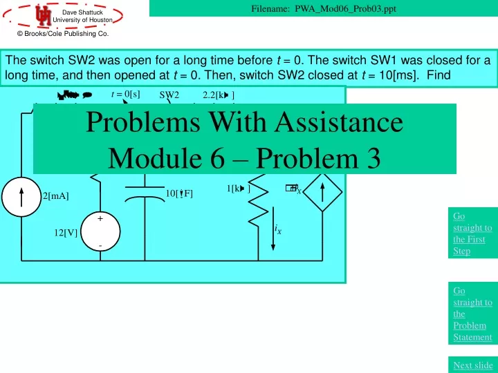
The switch SW2 was open for a long time before t = 0. The switch SW1 was closed for a long time, and then opened at t = 0. Then, switch SW2 closed at t = 10[ms]. Find i X (20[ms]). Problems With Assistance Module 6 – Problem 3. Filename: PWA_Mod06_Prob03.ppt.

E N D
The switch SW2 was open for a long time before t = 0. The switch SW1 was closed for a long time, and then opened at t = 0. Then, switch SW2 closed at t = 10[ms]. Find iX(20[ms]). Problems With AssistanceModule 6 – Problem 3 Filename: PWA_Mod06_Prob03.ppt Go straight to the First Step Go straight to the Problem Statement Next slide
Overview of this Problem In this problem, we will use the following concepts: • Defining Equations for Capacitors • RC Natural Response Go straight to the First Step Go straight to the Problem Statement Next slide
Textbook Coverage The material for this problem is covered in your textbook in the following sections: • Circuits by Carlson: Sections #.# • Electric Circuits 6th Ed. by Nilsson and Riedel: Sections #.# • Basic Engineering Circuit Analysis 6th Ed. by Irwin and Wu: Section #.# • Fundamentals of Electric Circuits by Alexander and Sadiku: Sections #.# • Introduction to Electric Circuits 2nd Ed. by Dorf: Sections #-# Next slide
Coverage in this Module The material for this problem is covered in this module in the following presentations: • DPKC_Mod06_Part01 • DPKC_Mod06_Part02 • DPKC_Mod06_Part03 • DPKC_Mod06_Part04 Next slide
Problem Statement The switch SW2 was open for a long time before t = 0. The switch SW1 was closed for a long time, and then opened at t = 0. Then, switch SW2 closed at t = 10[ms]. Find iX(20[ms]). Next slide
Solution – First Step – Where to Start? The switch SW2 was open for a long time before t = 0. The switch SW1 was closed for a long time, and then opened at t = 0. Then, switch SW2 closed at t = 10[ms]. Find iX(20[ms]). How should we start this problem? What is the first step? Next slide
The switch SW2 was open for a long time before t = 0. The switch SW1 was closed for a long time, and then opened at t = 0. Then, switch SW2 closed at t = 10[ms]. Find iX(20[ms]). Problem Solution – First Step • How should we start this problem? What is the first step? • Find the Thevenin equivalent seen by the capacitor. • Find the Norton equivalent seen by the capacitor. • Define the capacitive voltage. • Redraw the circuit for t < 0. • Redraw the circuit for t > 0.
Your Choice for First Step –Find the Thevenin equivalent seen by the capacitor The switch SW2 was open for a long time before t = 0. The switch SW1 was closed for a long time, and then opened at t = 0. Then, switch SW2 closed at t = 10[ms]. Find iX(20[ms]). This is not a good choice. It is not even clear what this means. There are two switching events, and as a result there may well be a different equivalent for each of the three time periods, t < 0, 0 < t < 10[ms], and t > 10[ms]. If we choose to find an equivalent, it will only be when we have identified a time period when no switching taking place. Please go back and try again.
Your Choice for First Step –Find the Norton equivalent seen by the capacitor The switch SW2 was open for a long time before t = 0. The switch SW1 was closed for a long time, and then opened at t = 0. Then, switch SW2 closed at t = 10[ms]. Find iX(20[ms]). This is not a good choice. It is not even clear what this means. There are two switching events, and as a result there may well be a different equivalent for each of the three time periods, t < 0, 0 < t < 10[ms], and t > 10[ms]. If we choose to find an equivalent, it will only be when we have identified a time period when no switching taking place. Please go back and try again.
Your Choice for First Step –Define the capacitive voltage The switch SW2 was open for a long time before t = 0. The switch SW1 was closed for a long time, and then opened at t = 0. Then, switch SW2 closed at t = 10[ms]. Find iX(20[ms]). This is the best choice for the first step. In almost all of these RC and RL circuits with switching, it is wise to solve first for the capacitive voltage or inductive current. This prevents problems finding initial conditions after switching take place, since these quantities cannot change instantaneously. Let’s define the capacitive voltage.
Your Choice for First Step –Redraw the circuit for t < 0 The switch SW2 was open for a long time before t = 0. The switch SW1 was closed for a long time, and then opened at t = 0. Then, switch SW2 closed at t = 10[ms]. Find iX(20[ms]). This is not the best choice for the first step. We will probably be doing this very shortly. However, in almost all of these RC and RL circuits with switching, it is wise to solve first for the capacitive voltage or inductive current. To find the capacitive voltage, we need to define the polarity for the voltage first. Please go back and try again.
Your Choice for First Step –Redraw the circuit for t > 0 The switch SW2 was open for a long time before t = 0. The switch SW1 was closed for a long time, and then opened at t = 0. Then, switch SW2 closed at t = 10[ms]. Find iX(20[ms]). This is not the best choice for the first step. We will probably be doing this later in the problem. However, in almost all of these RC and RL circuits with switching, it is wise to solve first for the capacitive voltage or inductive current. To find the capacitive voltage, we need to define the polarity for the voltage first. Please go back and try again.
Defining the Capacitive Voltage The switch SW2 was open for a long time before t = 0. The switch SW1 was closed for a long time, and then opened at t = 0. Then, switch SW2 closed at t = 10[ms]. Find iX(20[ms]). The polarity that we choose for this does not matter. However, choosing a polarity does matter. • We have defined the capacitive voltage. What should the second step be? • Solve for the current iX(t) in terms of the capacitive voltage. • Redraw the circuit for t < 0. • Apply source transformations. • Redraw the circuit for t > 0.
Your Choice for Second Step –Solve for the current iX(t) in terms of the capacitive voltage The switch SW2 was open for a long time before t = 0. The switch SW1 was closed for a long time, and then opened at t = 0. Then, switch SW2 closed at t = 10[ms]. Find iX(20[ms]). This is not a good choice for the second step. It is not even clear what this would mean, since the current iX is not even attached to the capacitive voltage until after switch SW2 closes at t = 10[ms]. The key here is to draw the circuit for a given time period, where the switches are all in known positions, and then solve. Please go back and try again.
Your Choice for Second Step –Redraw the circuit for t < 0 The switch SW2 was open for a long time before t = 0. The switch SW1 was closed for a long time, and then opened at t = 0. Then, switch SW2 closed at t = 10[ms]. Find iX(20[ms]). This is good choice for the second step, and the one that we will take. We want to draw the circuit for a given time period, where the switches are all in known positions, and then solve for quantities of interest. The quantity of interest here would be the initial value of the capacitive voltage, at t = 0. Redrawing for t < 0 helps us find that, since that voltage will not change when switch SW1 opens, since it is a capacitive voltage. Let’s go ahead and redraw the circuit.
Your Choice for Second Step –Apply source transformations The switch SW2 was open for a long time before t = 0. The switch SW1 was closed for a long time, and then opened at t = 0. Then, switch SW2 closed at t = 10[ms]. Find iX(20[ms]). This is not a good choice for the second step. We could do this, but we would be getting ahead of ourselves. The key here is to draw the circuit for a given time period, where the switches are all in known positions, and then solve. Please go back and try again.
Your Choice for Second Step –Redraw the circuit for t > 0 The switch SW2 was open for a long time before t = 0. The switch SW1 was closed for a long time, and then opened at t = 0. Then, switch SW2 closed at t = 10[ms]. Find iX(20[ms]). This is good choice for the second step, but is not the one that we will take. We want to draw the circuit for a given time period, where the switches are all in known positions, and then solve for quantities of interest. One quantity of interest here would be the initial value of the capacitive voltage, at t = 0. Redrawing for t < 0 helps us find that, since that voltage will not change when switch SW1 opens, since it is a capacitive voltage. We could solve for something else first, but it seems to make sense to do t < 0 and then t > 0. Let’s go ahead and redraw the circuit.
Redrawing the Circuit for t < 0 The switch SW2 was open for a long time before t = 0. The switch SW1 was closed for a long time, and then opened at t = 0. Then, switch SW2 closed at t = 10[ms]. Find iX(20[ms]). We have redrawn the circuit for t < 0 in the circuit at right, above. Note that switch SW1 was closed during this time, and switch SW2 was open. Since switch SW2 was open, the circuit to the right of that switch has no effect, and has been omitted here. Note also that the capacitive voltage vC has been labeled as vC(0), since it must be the same value with the switching at t = 0. Let’s find vC(0). The capacitor has been redrawn as an open circuit, since the circuit was in this condition for a long time, and had the opportunity to reach a steady-state condition.
Solving for vC(0) The switch SW2 was open for a long time before t = 0. The switch SW1 was closed for a long time, and then opened at t = 0. Then, switch SW2 closed at t = 10[ms]. Find iX(20[ms]). To solve for vC(0), we recognize that the current through the 3.3[kW] resistor is 2[mA], and write Next Slide
What is the Third Step? The switch SW2 was open for a long time before t = 0. The switch SW1 was closed for a long time, and then opened at t = 0. Then, switch SW2 closed at t = 10[ms]. Find iX(20[ms]). • We have found the initial condition we wanted. What should be the third step? • Redraw for t > 0. • Redraw for 0 < t < 10[ms]. • Redraw for t > 10[ms].
Your Choice for Third Step –Redraw for t > 0 The switch SW2 was open for a long time before t = 0. The switch SW1 was closed for a long time, and then opened at t = 0. Then, switch SW2 closed at t = 10[ms]. Find iX(20[ms]). This is not a good choice for the third step. It is not even clear what this would mean, since the switch SW2 closes at t = 10[ms]. The key here is to draw the circuit for a given time period, where the switches are all in known positions, and then solve. The time period given here does not meet this criterion, since switch SW2 moves in this time period. Please go back and try again.
Your Choice for Third Step –Redraw for 0 < t < 10[ms] The switch SW2 was open for a long time before t = 0. The switch SW1 was closed for a long time, and then opened at t = 0. Then, switch SW2 closed at t = 10[ms]. Find iX(20[ms]). This is the best choice for the third step. This is the time period for the next time of interest. During this time period, no switches close or open. Note that in this time period, both switches are open. Let’s redraw for this time period.
Your Choice for Third Step –Redraw for t > 10[ms] The switch SW2 was open for a long time before t = 0. The switch SW1 was closed for a long time, and then opened at t = 0. Then, switch SW2 closed at t = 10[ms]. Find iX(20[ms]). This is a good choice for the third step, but it is not the choice that we will choose. During this time period, no switches close or open. However, it just seems reasonable to work through the problem chronologically, and so the time period 0 < t < 10[ms] makes sense as the next period to consider. In addition, the initial condition for the last time period will be obtained from the time period 0 < t < 10[ms]. Let’s redraw for this time period.
Redrawing the Circuit for 0 < t < 10[ms] The switch SW2 was open for a long time before t = 0. The switch SW1 was closed for a long time, and then opened at t = 0. Then, switch SW2 closed at t = 10[ms]. Find iX(20[ms]). The capacitor has been redrawn as a capacitor, since it the circuit has not had a chance to reach a steady-state condition. We have redrawn the circuit for 0 < t < 10[ms] in the circuit at right, above. Note that switch SW1 and switch SW2 are open during this time. Since switch SW2 was open, the circuit to the right of that switch has no effect, and has been omitted here. Since switch SW1 was open, the circuit to the left of that switch has no effect, and has been omitted here. Let’s find vC(t) for 0 < t < 10[ms]. In fact, as we shall see, this kind of a circuit is a special case. It is not one of our six basic circuits, so does not have an exponential response.
Solution for 0 < t < 10[ms] The switch SW2 was open for a long time before t = 0. The switch SW1 was closed for a long time, and then opened at t = 0. Then, switch SW2 closed at t = 10[ms]. Find iX(20[ms]). The key at this point is to recognize that there is no current through the capacitor for this time period. As a result, the voltage across the capacitor cannot change. Remember that Next Slide
Solution for 0 < t < 10[ms], Note 1 The switch SW2 was open for a long time before t = 0. The switch SW1 was closed for a long time, and then opened at t = 0. Then, switch SW2 closed at t = 10[ms]. Find iX(20[ms]). Next Slide Note that we use the symbol £ in this solution, since it is for a capacitive voltage. A capacitive voltage up to the time of switching, must be valid at the time of switching, too, since it cannot change instantaneously. The key at this point is to recognize that there is no current through the capacitor for this time period. As a result, the voltage across the capacitor cannot change. Remember that
Solution for 0 < t < 10[ms], Note 2 The switch SW2 was open for a long time before t = 0. The switch SW1 was closed for a long time, and then opened at t = 0. Then, switch SW2 closed at t = 10[ms]. Find iX(20[ms]). Next Slide Some students become so fixated on RL and RC exponential responses that they begin to assume that all circuits fit into this response. Note that when we derived the exponential response equation, we did so only for six circuits, and for circuits that reduce to one of those six circuits. This circuit does not reduce to any of those. In these cases, it is necessary to go back to the basic defining equations for inductors and capacitors, which is what we did to get the solution below.
What is the Fourth Step? The switch SW2 was open for a long time before t = 0. The switch SW1 was closed for a long time, and then opened at t = 0. Then, switch SW2 closed at t = 10[ms]. Find iX(20[ms]). • We have found the initial condition we wanted. What should be the fourth step? • Solve for iX(t) for 0 < t < 10[ms]. • Replace the capacitor with an open circuit for t > 10[ms]. • Replace the capacitor with a voltage source for t > 10[ms]. • Redraw for t > 10[ms].
Your Choice for Fourth Step –Solve for iX(t) for 0 < t < 10[ms] The switch SW2 was open for a long time before t = 0. The switch SW1 was closed for a long time, and then opened at t = 0. Then, switch SW2 closed at t = 10[ms]. Find iX(20[ms]). This is not a good choice for the fourth step. We could certainly solve for iX(t) for 0 < t < 10[ms]. We have all the information that we would need to do this. However, we are not asked for this solution, and it will not help us find the solution for t > 10[ms], since this current can change instantaneously when switch SW2 closes at t = 10[ms]. Please go back and try again.
Your Choice for Fourth Step –Replace the capacitor with an open circuit for t > 10[ms] The switch SW2 was open for a long time before t = 0. The switch SW1 was closed for a long time, and then opened at t = 0. Then, switch SW2 closed at t = 10[ms]. Find iX(20[ms]). This is not a good choice for the fourth step. This would not be a valid step. For t > 10[ms], we have no reason to believe that the circuit will be in a steady-state condition. In fact, it will not be. Only when nothing is changing can the capacitor be replaced by an open circuit. Please go back and try again.
Your Choice for Fourth Step –Replace the capacitor with a voltage source for t > 10[ms] The switch SW2 was open for a long time before t = 0. The switch SW1 was closed for a long time, and then opened at t = 0. Then, switch SW2 closed at t = 10[ms]. Find iX(20[ms]). This is not a good choice for the fourth step. This would not be a valid step. For t > 10[ms], the capacitor does not behave like a voltage source. A voltage source holds its voltage, independent of the current through it. For a capacitor, the voltage is a function of the integral of the current. In some solution techniques, a capacitor is considered as a voltage source, but only under very specific conditions. We believe that this can be misleading if not understood completely, and recommend that this not be done at this point. Please go back and try again.
Your Choice for Fourth Step –Redraw the circuit for t > 10[ms] The switch SW2 was open for a long time before t = 0. The switch SW1 was closed for a long time, and then opened at t = 0. Then, switch SW2 closed at t = 10[ms]. Find iX(20[ms]). This is the best choice for the fourth step. We need to have the circuit that is valid after the next set of switching. This will allow us to solve for the capacitive voltage for t > 10[ms], and in addition, for iX(t) for t > 10[ms]. Let’s redraw the circuit for that time period.
Redrawing the Circuit for t > 10[ms] The switch SW2 was open for a long time before t = 0. The switch SW1 was closed for a long time, and then opened at t = 0. Then, switch SW2 closed at t = 10[ms]. Find iX(20[ms]). Here we have the circuit for the third time period. We should note that if we were to take the Thevenin equivalent with respect to the capacitor, we would have a natural response circuit. Note that there is no independent source, so that Thevenin voltage, as seen by the capacitor, would be zero. We already have the initial condition for this time period, so all we need is the Thevenin resistance, which will give us the time constant. Let’s find this resistance.
Finding the Thevenin Resistance The switch SW2 was open for a long time before t = 0. The switch SW1 was closed for a long time, and then opened at t = 0. Then, switch SW2 closed at t = 10[ms]. Find iX(20[ms]). We want to find the Thevenin equivalent with respect to the capacitor. We have a dependent source present, so it is advisable to apply a test source, in place of the capacitor. Note that we have no independent sources present, so we do not need to set any independent sources equal to zero. Let’s apply a test source.
Applying a Test Source The switch SW2 was open for a long time before t = 0. The switch SW1 was closed for a long time, and then opened at t = 0. Then, switch SW2 closed at t = 10[ms]. Find iX(20[ms]). We have applied a test current source, with a value of 1[A]. To solve for vT, we can apply KCL to the top node, and get Next, we will use KVL to find vT.
Writing KVL Around Loop The switch SW2 was open for a long time before t = 0. The switch SW1 was closed for a long time, and then opened at t = 0. Then, switch SW2 closed at t = 10[ms]. Find iX(20[ms]). Writing KVL around the loop, we get Next, we will use this resistance to find the time constant, t.
Finding the Time Constant The switch SW2 was open for a long time before t = 0. The switch SW1 was closed for a long time, and then opened at t = 0. Then, switch SW2 closed at t = 10[ms]. Find iX(20[ms]). Now, with this, we have the time constant, as Finally, we have everything we need to find vC(t).
Finding vC(t) The switch SW2 was open for a long time before t = 0. The switch SW1 was closed for a long time, and then opened at t = 0. Then, switch SW2 closed at t = 10[ms]. Find iX(20[ms]). We can substitute what we know into the equation for vC(t), Finally, we have everything we need to find iX(20[ms]).
Finding iX(20[ms]) The switch SW2 was open for a long time before t = 0. The switch SW1 was closed for a long time, and then opened at t = 0. Then, switch SW2 closed at t = 10[ms]. Find iX(20[ms]). We use KCL to solve for the current through the 2.2[kW] resistor in terms of iX. Then, using KVL, we can write an expression for iX(20[ms]). We get our solution on the next slide.
The Solution for iX(20[ms]) The switch SW2 was open for a long time before t = 0. The switch SW1 was closed for a long time, and then opened at t = 0. Then, switch SW2 closed at t = 10[ms]. Find iX(20[ms]). Solving, we have Go to the Comments Slide
How do I know whether a solution will be exponential or not? • The key is to look at the circuit, and determine whether it can be reduced, through equivalent circuits, to one of the six circuits that we described as having single time constant, exponential solutions. • However, in the special cases, we will get a clue if we try to use this solution technique when it doesn’t work. If we had solved for the REQ during the time 0 < t < 10[ms], we would have seen that REQ = infinity, which would give an infinite time constant. This is not possible, and is a clue that we have chosen the wrong approach. Go back to Overviewslide.