Download
1 / 20
200 likes | 213 Views
P08222 – FSAE Engine Management System. Erich Fiederlein (EMEN). Project Information. Project Name FSAE Engine Management System Project Number P08222 Project Family FSAE Autosports Family Track Vehicle Systems Technology Track Start Term 2007-2 planned academic quarter for MSD1

E N D
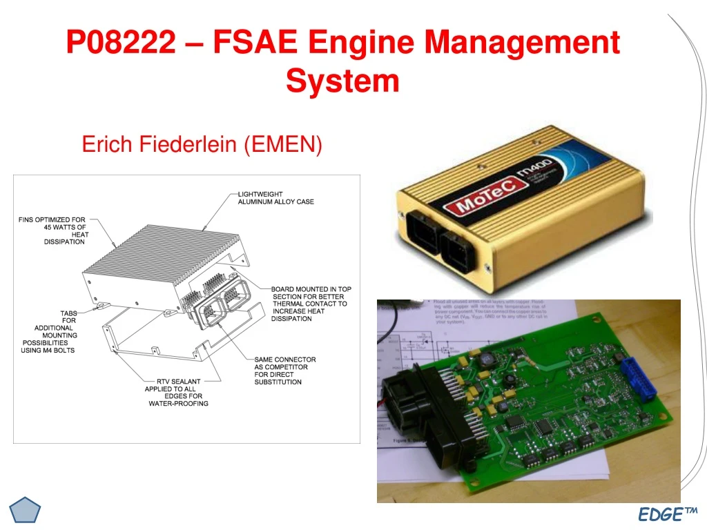
P08222 – FSAE Engine Management System Erich Fiederlein (EMEN)
Project Information • Project Name • FSAE Engine Management System • Project Number • P08222 • Project Family • FSAE Autosports Family • Track • Vehicle Systems Technology Track • Start Term • 2007-2 planned academic quarter for MSD1 • End Term • 2007-3 planned academic quarter for MSD2 • Faculty Guide • Dr. Alan Nye (ME) - confirmed • Faculty Consultant • Mr. Chris Deminco (ME) - confirmed • Faculty Consultant • Mr. George Slack (EE) - confirmed • Primary Customer • RIT FSAE Racing Team - confirmed
Phase 0: PlanningMission Statement Product Description • The high cost of high performance engine control units creates the desire for an 'in-house' unit. Sponsored by RIT's Formula SAE Racing team, this project is the second phase of several, which is intended to continue and expand upon the ECU project started last year. With an RIT made engine management system, which is based on MoTeC's M400 ECU, the formula team can significantly cut costs and gain recognition for their uniqueness in design. In addition, the ECU is designed and customized specifically for the RIT formula car, which can allow for greater freedoms in tuning, inputs, outputs, and data collection. Key Business Goals The primary business goals of this product are to • Provide the FSAE team with innovative technology made by RIT students that will improve their performance at competition. • Provide an open ended product that other senior design teams or the FSAE team can expand upon. • Reduce the cost incurred when purchasing a unit in the market. Primary Market The primary market for the ECU is the Formula SEA Racing team. Secondary Market Secondary markets for the ECU include other motorsports projects/teams such as the Mini Baja team. Stakeholders Stakeholders in the design of our product include the following: The RIT FSAE Racing team The faculty consultants and guides The Society of Automotive Engineers The sponsors of the RIT FSAE Racing team The Kate Gleason College of Engineering
Phase 0: PlanningStaffing Requirements Mechanical Engineers Number: 2 It will be the responsibility of the Mechanical Engineers to design and develop a test bench for the engine management system. In order to test the unit properly we will need to develop a tool that will simulate the inputs and outputs of the system (ie. A running engine). These engineers should have an understanding of how engines operate with regards to sensor and communication to and from the engine controller. Electrical Engineers Number: 3 The groundwork has been laid for this project already and we are not trying to reinvent the wheel. The Electrical Engineers job will be to learn what the previous team accomplished and expand upon their design. These engineers should have a strong background in circuit design and should be able to debug and troubleshoot circuitry. They should have experience in coding microcontrollers, PCB layout tools, surface mount soldering tools, Power supplies, signal processing, DC-DC converters, noise filtering, etc. These engineers should also have knowledge of how engine management systems work and how their subsystem components work. Industrial and Systems Engineers Number: 1 This project will need extensive testing and confirmation before being used on a real engine. It will be the responsibility of the Industrial and Systems Engineers to develop a test plan based on the Formula teams requests and the requirements used in industry. These engineers should have some knowledge of how engines operate. They will also be responsible for assisting in the design of the test bench so that the design can accommodate all of the tests. Computer Engineers Number: 1 The integration of the ECU to the motor is of utmost importance in this project. It will be the responsibility of the Computer Engineer to assist the Electrical Engineers in developing the code for the microcontroller, and to help the software engineer in developing the graphical user interface (GUI) Software Engineers Number:1 The Integration of the ECU to the user is also of high importance in this project and it is the responsibility of this engineer to develop a graphical user interface (GUI) modeled after the Motec M400 software.
Phase 0: PlanningResource Requirements People The FSAE team project manager and engine group leader will be heavily relied upon for information and requirements. Chris Deminco of Delphi is a valuable source of knowledge and experience from industry. ME, EE, and CE professors will also be useful as resources for this project. The members of the past senior design team will be a valuable source of information Environment A dedicated workspace will be necessary as elaborate testing and debugging setups will be used. Space in the Senior Design lab on the 3rd floor of the Engineering building is necessary. This space will have to be reserved at the beginning of the SD1 Equipment Machine shop equipment such as mills, lathes, etc. will be needed for machining Electrical Engineering test equipment such as scope, multi-meters, power supplies, etc. will be required. Computers for coding will be necessary to test/run and develop code A development board has already been purchased for this project. A 10 Amp power supply would be helpful but a car battery with a charger would work as well. The CIMS Surface mounting PCB equipment is necessary for populating boards Materials More chips will likely be needed as time goes on. Materials to build the test bench will be needed Sensors and other devices will also be needed for the test bench but will likely come from Formula team supplies.
Phase 1: Concept DevelopmentIdentify Customer Needs - Interviews Primary Customer(s) Last years FSAE team project manager indicated that developing a test bench is a necessary step. He feels that the project should continue where the other team left it and should not be redesigned. The teams deliverables should include a test bench that will simulate an engine, and a proposal, with proof, of a fixed ECU. It is not the goal of this SD team to remake the ECU, that will be the goal of the next SD team. This will help keep the scope of the project reasonable for a senior design team. Other Stakeholder(s) I have interviewed the faculty guide for this project and the FSAE team. He indicated that developing a test bench for the ECU would be an important component for the project. He also indicated that their would likely be another senior design team to finish the ECU development next year. Past Senior Design Team(s) I was the project manager for last years team. I have all of the documentation from the past team. The FSAE team has the ECU prototype that was developed last year including all the extra chips and connectors that were purchased. I have interviewed the lead EE of last years project who gave some more advice as to how to debug the ECU. He indicated that a 10 amp power supply would be useful in debugging the power supply circuitry. He noted that it could be done with a car battery but the power conditioning circuitry would need to be tested first so the correct amount of power goes to the correct circuitry. Also the battery would have to be kept charged which would be the responsibility of the SD team.
Phase 1: Concept DevelopmentIdentify Customer Needs - Benchmarking Competitive or Cooperative Solutions Extensive benchmarking was done by last years team when developing the ECU. We also took the input from the formula team members and incorporated their requests into the design. The graphical user interface that the team will develop should be modeled after the one currently used by the FSAE team. That software, created by MOTEC, is already used by the FSAE team and is readily available for benchmark. A detailed list of customer needs and specs can be found at P07222 website. Internet and Technical Literature Search • [1] Bosch, R., 1999, Gasoline-engine management, Robert Bosch GmbH, Stuttgart, Germany. • [2] Bosch, R., 2001, "Technical Customer Information: Planar Wide Band Lambda Sensor," Robert Bosch GmbH, Stuttgart, Germany. • [3] "Oxygen Sensors," Service Tech Magazine, May, 2001, pp. 13-15. • [4] Tech-Edge, 2007, "How 5-Wire Sensors Work," http://wbo2.com/lsu/lsuworks.htm • [5] M400 System Specifications MoTeC Pty Ltd. 2003. m400specs.pdf. • [6] MoTeC M400/M600/M800/M880 User's Manual MoTeC Pty Ltd, 2001-2003. pp. 1-101 • [7] Linear Technologies Schematic Screenshot from SWCAD Program simulation. • [8] www.motec.com • [9] www.autronic.com • [10] www.sae.org • [11] www.howstuffworks.com
Phase 1: Concept DevelopmentIdentify Customer Needs – Hierarchy Needs Statements: • Debug the ECU. • Pick up where the last team left off • Debug the current design • Propose a solution to fix the circuitry in the prototype • Prove that the solution will work by demonstrating it on the test bench. • Create a test bench to help develop the ECU. • Test bench must have sensors that support ECU operation • Must be representative of an actual engine • Should have outputs for proof of concept • Create a graphical user interface (GUI). • Modeled after the Motec ECU interface • Should be easy to use and update • Show that the ECU can be updated from the GUI • Develop a test plan so the ECU can be validated. • Thorough testing must be completed before placing on an engine • Research regulations for testing ECU’s • Keep good documentation • This project will be handed on to the next team so good documentation is essential • A detailed list of customer needs and specs can be found at the P07222 website.
Issues and Risks • Having a team that is not skilled enough or does not have the drive to complete a difficult task such as this • Being unable to get lab space • Not remembering to charge the battery for use at the next session. • Danger from having a car battery lying around • Lead times of parts • Aligning resources with the formula team
Future Plan Continue to recruit team members for this project. Present this presentation to the new SD team and answer any questions about the project that may arise from it. Help the team get the information that was left by the last team along with the materials/prototypes. Finish touching up PRP