Download
1 / 19
190 likes | 368 Views
Outline Synthesis Procedure Example Domain-Specific Synthesis Silicon Compilers Example Tools Goal Understand behavioral synthesis algorithms Overview behavioral synthesis tools. Behavioral Synthesis. Compilers have been around for years, why not HLL compilers? Complicated constraints

E N D
Outline Synthesis Procedure Example Domain-Specific Synthesis Silicon Compilers Example Tools Goal Understand behavioral synthesis algorithms Overview behavioral synthesis tools Behavioral Synthesis
Compilers have been around for years, why not HLL compilers? Complicated constraints timing constraints bus protocols pipelining physical constraints registers and ALUs are expensive communications (muxes, wiring) is expensive packaging hierarchy Heterogeneity separation of data and control logic wide range of RTL primitives ALU, ROM, MUX Why is Behavioral Synthesis Hard?
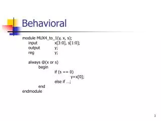
Parse behavioral description into data flow graph equivalent to compiler intermediate code Optimize data flow graph compiler-like operations Schedule operations assign operations to clock cycles (in synchronous system) Cluster operations group connected components together Allocate RTL resources place values in registers place operations in ALUs data transfers on wires and MUXs Generate control logic microcode, PLA, random logic fit to clock cycles Synthesis Procedure if (a == b) out = 1; else out = 0; reg + mux
Transform data flow minimize cost (operations) minimize delay (path length) Compiler-like transformations loop unrolling code motion strength reduction A A B C A B D B C D A A B A B Data Flow Optimization X +
Assign operations to clock cycles balance speed vs. cost 1 A 2 A 1 3 A A C 2 4 B C B 3 5 D D Scheduling • 3 clock cycles • 2 ALUs • 5 clock cycles • 1 ALU
Cluster operations based on connectivity connected components Uses guide later package partitioning guide binding to RTL modules guide chip place and route Clustering
Map data flow to RTL components allocate operator and register components bind operations and values to them minimize total cost of components Cost models cost for different operators cost for register bits determined by RTL implementation experience Approach NP-hard search problem related to graph covering cover data flow graph with RTL modules minimax - EMUCS maximum munching - like code generation tricky trade-offs e.g. adder and subtractor vs. one ALU A/B Allocation and Binding A B cost: 5
State Machine transformed along with data flow specify clock cycles, signal values inputs from conditionals outputs for muxes, ALUs, etc. Clocking gating clocks with control values generally a non-issue today Approach ROM microcode PLA state machines random logic state machines state assignment, optimization left for RTL synthesis Control Logic Generation S0 O=00 j=1 S1 O=01 k=4 k=0 S2 S3 O=10 O=11
4-bit Up/Down Counter 4-bit input "countin" 4-bit output "countout" up/down control "up" count control "count" internal state "i" implied clock Behavior up = 1 => count up up = 0 => count down count = 1 => count count = 0 => load 4 1 1 4 Synthesis Example countin up clock i count countout
Verilog Description /* ----- Programmable 4-bit up/down counter ----- */ MODULE COUNTER (COUNTIN: IN, UP: IN, COUNT: IN, COUNTOUT: OUT); EXTERNAL COUNTER; DCL COUNTIN BIT(4), /* programming input */ UP BIT(1), /* 1=up, 0=down */ COUNT BIT(1), /* 1=count, 0=program */ COUNTOUT BIT(4); /* counter output */ INTERNAL COUNTER; DCL I BIT(4); /* counting variable */ BODY COUNTER; DO INFINITE LOOP COUNTOUT:=I; IF COUNT THEN IF UP THEN I:=I+1; ELSE i:=I-1; ENDIF; ELSE I=COUNTIN; ENDIF; ENDDO; END COUNTER;
VHDL Description package vvectors is subtype bit32 is integer; subtype bit4 is integer range 0 to 15; subtype bit16 is integer range 0 to 65535; end vvectors; ... use work.vvectors.all; entity counter is port (clock : in bit; countin : in bit4; up, count : in bit; countout : out bit4); end counter;
VHDL Description cont. architecture behavior of counter is begin process variable i: bit4 := 0; begin wait until clock = '1'; countout <= i; if (count = '1') then if (up = '1') then if (i = bit4'high) then i := bit4'low; else i := i+1; end if; else if (i = bit4'low) then i := bit4'high; else i := i-1; end if; end if; else i := countin; end if; end process; end behavior;
Parsed Data Flow i loop start countout 1 1 + - if up countin if count i
Optimized and Scheduled Data Flow i cycle j countout +1 -1 if up + countin if count i cycle j+1
RTL Bindings +1 -1 mux up 1 4-bit adder 4-bit ALU add/sub (up) countin countin mux mux count count 4-bit reg 4-bit reg clock clock countout countout
RTL library the “instruction set” synthesis results strongly depend on it in example, really want up/down RTL module RISC approach does not apply since circuits are CISC ALU, adder, up/down counter, incrementer, ... Bottom-up feedback timing and cost information results can change radically with slightly different costs e.g. ALU cheaper, mux more expensive Synthesis Issues vs.
Limit synthesis to subset of behaviors instruction set processors digital signal processors analog signal processors state-machine controllers Specialized input language more precision Specialized transformations no control in DSP Specialized RTL library bit-serial DSP Examples CATHEDRAL I, II, III, IV LAGER Domain-Specific Synthesis
Map directly from behavior to layout developed at Caltech original focus on datapaths with PLA/ROM control tools often developed for specific chip project SCHEME chip at MIT OM1, OM2 at Caltech Simple optimization, scheduling, binding requires many user hints Primarily module generators direct RTL to layout synthesis Original idea died out too restrictive lives on in module generators, DSP synthesis Silicon Compilers
System Architect’s Workbench (CMU) VSS (UC Irvine) Olympus/Hercules (Stanford) Alliance (Univ. PMC) Yorktown Silicon Compiler (IBM) MIMOLA (Univ. Dortmund) BLIS (UCB) CATHEDRAL I..IV (Univ. Leuven) LAGER (UCB) Example Tools

![ECE-C662 [Knapp, “Behavioral Synthesis” Prentice-Hall 1996]](https://cdn3.slideserve.com/5491658/ece-c662-knapp-behavioral-synthesis-prentice-hall-1996-dt.jpg)