Download
1 / 25
250 likes | 360 Views
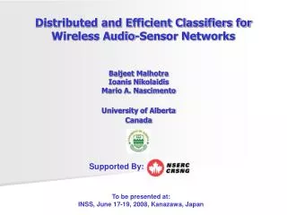
WIRELESS AUDIO. PRESENTED BY GROUP 246 JOHN CHRISTENSEN ZAINAB SANUSI DIPTESH PATEL. OVERVIEW. INTRODUCTION REQUIREMENTS OPTIONS CONSIDERED OUR FINAL DESIGN OPTION BUDGET PROGRESS TIMELINE. INTRODUCTION.

E N D
WIRELESS AUDIO PRESENTED BY GROUP 246 JOHN CHRISTENSEN ZAINAB SANUSI DIPTESH PATEL
OVERVIEW • INTRODUCTION • REQUIREMENTS • OPTIONS CONSIDERED • OUR FINAL DESIGN OPTION • BUDGET • PROGRESS • TIMELINE
INTRODUCTION A reliable and cost effective wireless microphone system is needed by the NDSU Electrical Engineering department. To achieve high reliability and stay within budget it was decided to purchase existing wireless microphone units and add modifications. - A “Smart” Control Unit will be added which will scan frequency channels of the existing wireless units, determine if there is interference, and automatically set receivers and transmitters to the best channels.
THE NEED? • Our system will be used by the NDSU Electrical and Computer Engineering Department for the technical seminars held by the VSTS scholar team.
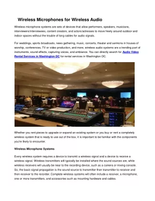
REQUIRMENTS • The collection site needs to be capable of receiving at least two sources. • At least some of the transmitters need to be able to conveniently attach to something like a lapel microphone. • The transmitters need to be able to operate without causing interference to one another.
REQUIREMENTS • The transmitters connected to the audio sources need to be battery operated and should provide some indication of battery condition. • Transmission range must be reliable and noise-free up to 70 feet. • The audio at the collection site needs to be in an appropriate form so that it can be routed (under adjustable gain) to a recording device or to the input of other audio-type equipment such as a mixer.
REQUIREMENTS • The transmitters need to meet FCC guidelines. • The system should be easy to set up and take down because of time limitations. • The collection site needs to be able to selectively transmit any of the received audio sources or an external audio source to an auxiliary sound system.
PREVIOUS WORK DONE SURE SLX4 • RETAILS FOR $760 • AUTO-FREQUENCY SELECT • SINGLE MIC OPERATION ELECTRO-VOICE N/DYM • RETAILS FOR $650 • AUTO-FREQUENCY SELECT • SINGLE MIC OPERATION
OPTIONS CONSIDERED Mic 1 Mic 2 Transmitter 1 Transmitter 2 Receiver 1 Receiver 2 Mixer 1 Receiver 1 Receiver 2 PA system Mixer 2 Recording Device DESIGN OPTION I • THIS DESIGN HAD TWO MIXERSBUT THERE WAS ONLY ONE MIXER AVAILABLE FOR USE. • IT WOULD ALSO REQUIRE FOUR RECEIVERS. • IT WAS NOT A COST EFFECTIVE OPTION. • BETTER SOUND QUALITY TO PA Control Unit
Mic 2 Mic 1 Transmitter 1 Transmitter 2 Receiver 1 Receiver 2 Audio Mixer Recording Device PA system OPTION CONSIDERED • DESIGN OPTION II • CONNECTION TO THE PA SYSTEM WOULD NOT HAVE BEEN WIRELESS • WE NEEDED ONLY TWO SETS OF RECEIVERS AND TRANSMITTERS Control Unit
Mic 1 Mic 2 Transmitter 1 Transmitter 2 Receiver 1 Receiver 2 Audio Mixer Recording Device Transmitter 3 Receiver 3 PA system OUR DESIGN OPTION Control Unit • COMPLETELY WIRELESS TRANSMISSIONS • MINIMUM RECEIVERS & TRANSMITTERS LINE IN
Highlighted Components • An ECE 405 group will be supplying the mixer. • ECE Department will supply the video camera and PA system
Radio Frequency Tuner 4-bit Shift Register Linear LT5537 RF Power Detector 7 Segment Displays 8 –bit Shift Register 7 Segment Displays 8 –bit Shift Register PIC16F877A Microcontroller 8 –bit Shift Register 7 Segment Displays 16 –bit Shift Register 4-bit Shift Register 4-bit Shift Register 4-bit Shift Register 16 interference indicating lights Receiver 1 Receiver 2 Transmitter 3 CONTROL UNIT FLOW CHART
Microcontroller • PIC16F877A • Previous use of brother PIC16F876 in Embedded Systems. • Cost Effective (free) • 33 I/O pins
Frequency Tuner • Plan is to use an additional wireless microphone receiver as a tuner to check the frequencies of interest for interference. • Or find commercially available frequency tuner.
RF Power Detector • LT5537 from Linear Technology • Wide Dynamic Range RF/IF Log Detector • 10Hz to 1000MHz operation • Sensitivity -76dBm or Better at 200MHz • Capable of outputting RSSI (Received Signal Strength Indication) in the form of a DC voltage
Power Sources • Main Control Unit Bundle (receiver 1&2, transmitter 3, mixer) and receiver 3– Wall Outlet • Wireless microphones – Batteries • Considering rechargeable batteries for all devices
WIRELESS MICROPHONE SYSTEMS WE ARE USING GEMINI UF2064ML DUAL SYSTEM GEMINI UX-16L • Operating frequency 790Mhz-806Mhz • Range ~ 300 ft • 16 common frequency channels
BUDGET • Gemini UF2064ML (Wireless hand mic, lapel mic, and dual receiver) ~ $230 • Gemini UX16L lapel mic and receiver ~ $90 • Carry Case ~ $40 • Frequency Tuner ~ $90 • Components (LED’s, et al) ~ $30 • Cables and connectors ~ $20 TOTAL COST ~ $500
WORK DONE SO FAR • RESEARCHED WIRELESS MICROPHONE SYSTEMS AND SELECTED ONE THAT BEST FITS OUR NEEDS • CHECKED FOR POSSIBLE INTERFERENCE • ORDERED WIRELESS MICROPHONE SYSTEMS FROM Etronics.com • A WORKING PROGRAM TO SHOW HOW THE PIC MICROCONTROLLER WILL AUTOMATICALLY SET THE FREQUENCY CHANNELS. • FOUND RF POWER DETECTOR IC
Drawbacks • Wireless Microphone systems were ordered six weeks ago and have not arrived • Without Microphone Systems we are left with unknowns • RF Power Detector chip is only available in hard to work with DDB package