Download

1 / 11
110 likes | 254 Views
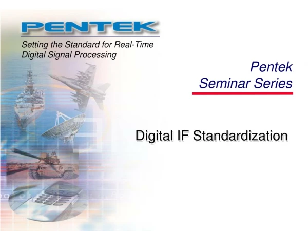
Digital IF Standardization. Digital IF Output. Signal Processing Array Switched Fabric. A/D. Tuner 1 1. A/D. Tuner 2. A/D. Tuner N. VME,cPCI, PCI, Ethernet,…. Industry Requirement.

E N D
Digital IF Output Signal Processing Array Switched Fabric A/D Tuner 1 1 A/D Tuner 2 . . . . . . . . . A/D Tuner N VME,cPCI, PCI, Ethernet,… Industry Requirement • During the last several years, many communication systems have been using digital methods for the last downconversion or first upconversion stage. • Often, the Intermediate Frequency (IF) output of an RF downconverter has been digitized using a high speed Analog to Digital Converter.
Digital IF Output Signal Processing Array Switched Fabric A/D Tuner 1 1 A/D Tuner 2 . . . . . . . . . A/D Tuner N VME,cPCI, PCI, Ethernet,… Transfer Methods • This digital data stream is then transferred to subsequent processing stages often in a proprietary and application-specific format. • Ribbon Cables, Backplanes, high-speed serial and optical methods have all been employed.
Desire for Standardization • Over the last several years, many large government and industrial customers of communication systems have been requesting the purveyors of RF receiver/transmitter equipment, Signal Digitization and Conversion equipment and Signal Processing equipment to standardize on a signal interconnect methodology. • It is desirable to standardize the format of the “Digital IF” used in these systems so that a marketplace of interoperable products can serve the SIGINT, Aerospace and other communications-oriented communities.
Industry Response • In 2004, an industry group led by Mercury Computer and DRS-Signal Solutions solicited participation from experienced companies in the signal acquisition and high performance computing community and met with some prominent customers of this technology. • The result was an initiative to work on a standard to be adopted by the VMEbus Trade Organization (VITA) widely respected in this community • The resulting on-going effort is VITA Standard 49.
Vita49 Scope of Effort The goal of the VITA 49.0 Standard effort is to develop a link agnostic protocol format for the transmittal of digital IF data between one or more sources and one or more destinations. This Standard will cover both receive and transmit data paths.
Applied Signal Technology (P) Bustronic Corporation (O) Curtiss Wright (P) DRS-Signal Solutions (S) Digital Receiver Technology (P) Dy 4 Systems (O) Echotek Corporation (P) Foxconn Electronics L3 Communications-Integ Sys (O) Mercury Computer Systems (S) Pentek (S) VITA 49: Present Participants • Pentland Systems (P) • Praxis Engineering Technologies (P) • SBS Technologies (O) • Spectrum Signal Processing (S) • Synergy Microsystems (O) • Systran Corporation (P) • Transtech DSP (O) • Tyco Electronics (O) • VISTA Controls Corporation (O) • VMETRO (O) (S) = Sponsor (P) = Participant (O) = Observer
Link Agnostic • In order to support emerging Switched Fabric interconnects as well as traditional methods we need a portable protocol. • The protocol must enable necessary communication system requirements such as phase alignment of multiple local oscillators, time stamping and receiver/transmitter control. • Finally, this protocol must support multiple interconnect methods, such as gigabit links and serial switched fabrics. • A Packet or Data Frame methodology is the most portable and flexible.
Top Down Digital IF Interface Standard Bottom up Two Pronged Development • Top Down • System level requirements • Bottom Up • Awareness of physical implementation • Try to keep it simple
Requirements Overview • Data Plane Standard Only • Augment existing infrastructure for control and status • Status information may be passed with Data • Data Plane • High Bandwidth • Channel Bonding • Minimal Implementation Resources • One-way Data Plane • Embedded Meta-data • Data Framing & Synchronization • Error Detection – rely on link standard • Low Latency • Data Distribution • Short and Long distances
Packet Definition is The Standard Header Additional Data Payload Data • Data Frame can contain: • Header: Information required for the correct processing and/or data distribution of the sensor data • Additional Data: Information to be associated with this frame of data for downstream processing (meta-data) • Payload Data: Actual data for this frame • The work of the VITA 49 Working Group is to define a packet structure that when conveyed by an appropriately high speed interconnect can replace aging methods of configuring a digital communication system.