Download
1 / 6
60 likes | 71 Views
M- Reg. LDM. Input. Reg Addr. LD1. M1. OpCode. Reg File. 4-bit Reg. M U X. enable. enable. enable. WR. ER. A L U. WM. 4-bit Reg. M U X. Mem Unit. Mem Addr. EM. LD2. M2. Operations on data path. ALU ports can get input from any of the two registers

E N D
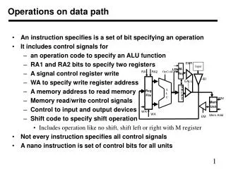
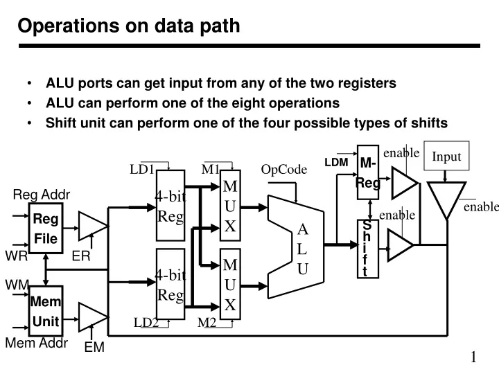
M- Reg LDM Input Reg Addr LD1 M1 OpCode Reg File 4-bit Reg M U X enable enable enable WR ER A L U WM 4-bit Reg M U X Mem Unit Mem Addr EM LD2 M2 Operations on data path • ALU ports can get input from any of the two registers • ALU can perform one of the eight operations • Shift unit can perform one of the four possible types of shifts S h i f t
ALU operations and data transfers • ALU operations are • 000 Output A 100 A + B • 001 Output B 101 A - B • 010 Output 00..0 110 A and B • 011 Output 11..1 111 A or B • Shift Operation • 00 Shift left without M 10 Shift left with M • 01 shift right without M 11 Shift left with M • On the main bus, we can enable output of ALU, M-register, Input, Register File, and Memory unit (only one of them at a time) • The main bus data data can be written into the two registers, Register File, and Memory unit • ALU output can also be written into M register
Some actual transfers • To transfer Input to any register • Enable input to main bus • Write in register by enabling LD1 or LD2 • Other control signals should be asserted in such a way so that they do not cause any change in state • To transfer a register data to M register • Select register through one of the multiplexers • Select ALU operation to transfer selected port to output • Write in M register by asserting LDM signal • To transfer Register file or memory unit output to a register • Select appropriate register in Register file or memory location in memory and enable appropriate unit output to bus • Write in a register using LD1 or LD2
M- Reg LDM RA1 RA2 Input OpCode Reg File EMR EALU A L U EI S H I F T WM Mem Unit WR WA Mem Addr EM Modified Data Path • We can eliminate some components in the data path • For example two registers and multiplexers may not be needed • The register file is two ported Shift code
Register File • Register file contain R registers • R can be 4 or 8 or 16 or 32 • Each register has n bits (n can be 4, 8, 16, or 32) • n defines the data path width • Register file has two R-to-1 n-bit multiplexers • Each multiplexer multiplexes all register to select one to output • Any register can be read out on any of the two ports • Each multiplexer needs a log R bits address (RA1 or RA2) • Any register can be written using data on the bus • Write address is specified by WA (log R bits) • Write is enabled by WR signal
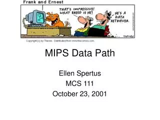
Operations • An instruction specifies is a set of bit specifying an operation • It includes • an operation code to specify an ALU function • RA1 and RA2 bits to specify two registers • WA to specify which register to write back • shift code to specify shift operation • Includes operation like no shift, shift left or right with M register • Memory address and control to read or write memory • Not every instruction specifies all instructions • A nano instruction is set of control bits for all units